Electropneumatic brake system for a towed vehicle

a technology of towed vehicles and brake systems, applied in the direction of brake systems, etc., can solve the problems of relatively complex configurations and drivers may notice the tipping process too late, and achieve the effect of stable function and higher axle load

Active Publication Date: 2016-05-10
ZF CV SYST EURO BV
View PDF7 Cites 3 Cited by
  • Summary
  • Abstract
  • Description
  • Claims
  • Application Information

AI Technical Summary

Benefits of technology

[0014]The axle having the second modulator can be a rear axle and the axle having the first modulator can be a front axle. This arrangement can also be provided in a reversed manner and is dependent, in particular, on the typical load distribution along the towed vehicle. A stability function in the region of the axle with the higher axle load is advantageous.
[0015]A connecting line can be provided between the control line to the second modulator on one side and the control line on the first modulator on the other side, with a valve for shutting off the connecting line in the case of a higher pressure in the control line at the first modulator than in the control line to the second modulator. As a result, a pressure difference between the two control lines is avoided as long as brake pressure does not prevail in the control line at the first modulator.

Problems solved by technology

This type of configuration is relatively complex, however.
If a towed vehicle navigates a band in the roadway too rapidly, the towed vehicle can turn over and drag the towing vehicle or the tractor vehicle with it or can become detached therefrom.
In such a situation, the driver may notice the tipping process too late—namely, not until the driving behavior of the traction engine is affected.

Method used


Image

  • Electropneumatic brake system for a towed vehicle
  • Electropneumatic brake system for a towed vehicle
  • Electropneumatic brake system for a towed vehicle

Examples


Embodiment Construction

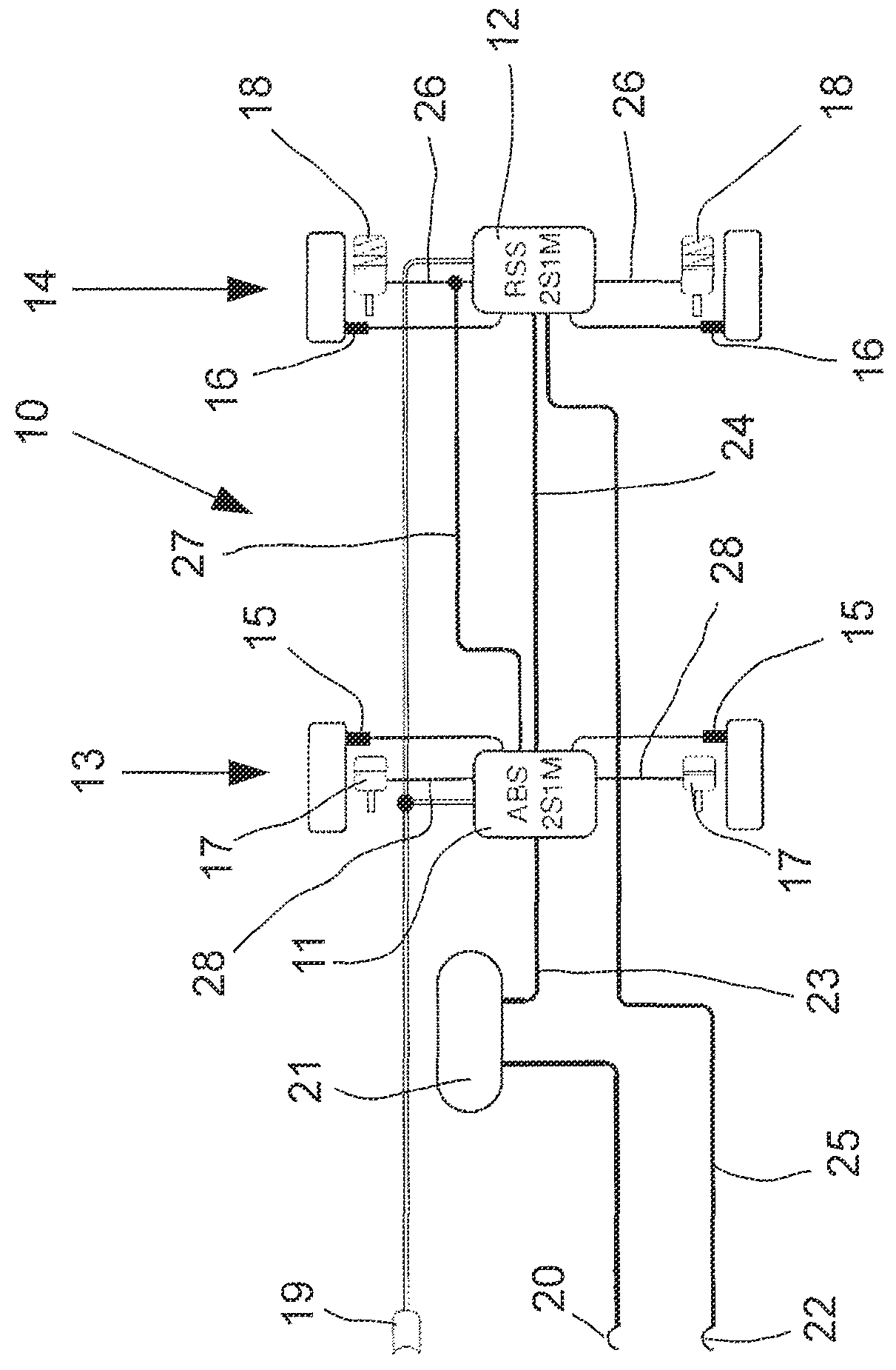
[0024]A brake system 10 according to FIG. 1 contains two 2S1M configurations. Each of the two configurations contains a modulator 11, 12 with an electronic regulator and pneumatic components. Modulator 11 is assigned to a front axle 13, and modulator 12 is assigned to a rear axle 14. Both modulators 11, 12 control an anti-lock ABS function for the respectively associated axle 13, 14. To this end, in each case two wheel speed sensors 15, 16 transmit signals to modulators 11, 12. The latter control the brake pressure in connected wheel brake cylinders 17, 18.

[0025]Modulators 11, 12 are connected via a coupling 19 (here, for example, according to the U.S. standard SAE J 560) to a power supply of a tractor vehicle (not shown). Electrical control signals are not transmitted from the tractor vehicle.

[0026]Compressed air at reservoir pressure passes via a pneumatic coupling 20 into a reservoir tank 21. In an analogous manner, control pressure is fed from the tractor vehicle to brake system...


PUM


Abstract

In an electropneumatic brake system for a towed vehicle having at least two axles, such as a drawbar trailer, one axle is assigned a first modulator at least with an anti-lock function and another axle is assigned a second modulator at least with an anti-lock function and an additional function. Both modulators are connected to a reservoir pressure, and both modulators load wheel brake cylinders via brake pressure lines. The second modulator is connected to a control line and the first modulator has a connector for a control line. A control line leads from the connector for the control line on the first modulator to the brake pressure line between the second modulator and at least one of its wheel brake cylinders.

Description

CROSS-REFERENCE TO RELATED APPLICATION[0001]This application claims priority to / the benefit of DE 10 2013 021 681.8 filed on Dec. 19, 2013, the disclosure of which is hereby incorporated herein by reference in its entirety.FIELD OF THE INVENTION[0002]The present invention generally relates to electropneumatic brake systems for towed vehicles.BACKGROUND OF THE INVENTION[0003]Commercial vehicles have pneumatic brake systems that are linked to electronically controlled functions in order to improve safety. Herein, the overall system is referred to as an electropneumatic brake system. A stipulated constituent part of brake systems in commercial vehicles is an anti-lock function in many countries.[0004]The anti-lock function can be realized in different ways. In one simple embodiment for two axles, the rotational speeds of the wheels of the two axles are detected. Each wheel is assigned a rotational speed sensor, and each axle is assigned a dedicated modulator with a control unit. Each a...

Claims


Application Information

Patent Timeline
Patent Type & Authority Patents(United States)
IPC IPC(8): B60T8/17B60T8/1761B60T8/176B60T8/1755
CPCB60T8/1708B60T8/176B60T8/1755B60T8/17616
Inventor STENDER, AXELWEIHE, ULRICH
Owner ZF CV SYST EURO BV
Why Eureka
Try Eureka