Eureka AIR delivers breakthrough ideas for toughest innovation challenges, trusted by R&D personnel around the world.

Reverse osmosis system

a reverse osmosis and pump technology, applied in reverse osmosis, machines/engines, membranes, etc., can solve the problem of too short time available for pressure exchange, and achieve the effect of preventing pressure differences over displacement pumps

Active Publication Date: 2016-08-16
DANFOSS AS
View PDF40 Cites 2 Cited by
  • Summary
  • Abstract
  • Description
  • Claims
  • Application Information

AI Technical Summary

Benefits of technology

[0008]A displacement pump is a pump with a positive displacement, in which the fluid is transported through closed volumes. In other words a displacement pump has a constant feed performance for each work cycle. A work cycle can, for example be a rotation or a piston stroke or the like. Examples of displacement pumps are, piston, gear wheel, gerotor, orbit, membrane, hose, peristaltic, screw, spindle, eccentric screw or vane pumps, this list not being complete. A displacement pump has a known efficiency and a sufficiently linear characteristic between the speed and the pump output, that is, the supplied volume. Contrary to this, pumps that do not work with closed volumes have no linear dependence between the speed and the pump output. For example, centrifugal pumps, jet and turbine pumps belong to this category, but also this list is not complete. Compared with a centrifugal pump, the energy consumption of a displacement pump is small. Thus, an energy saving can be achieved in relation to the centrifugal pumps used in reverse osmosis systems until now. For a large flow, a centrifugal pump requires a much higher speed than a displacement pump. If the pressure exchanger is mounted on the same shaft, it has to run with the same high speed. This may cause that the time available for a pressure exchange is too short. A further advantage is that with a displacement pump the flow the pressure exchanger can be controlled in a substantially more accurate manner that until now. This flow is substantially a linear function of the speed of the displacement pump. Accordingly, it can easily be achieved that by means of the pressure exchanger as much feed water as possible can be acted upon by the pressure of the concentrate. On the other hand, however, it can be avoided that concentrate is transported through the pressure exchanger and then back into the inlet of the membrane unit. Accordingly, a mixing of feed water and concentrate can practically be avoided, which has a positive influence on the efficiency.
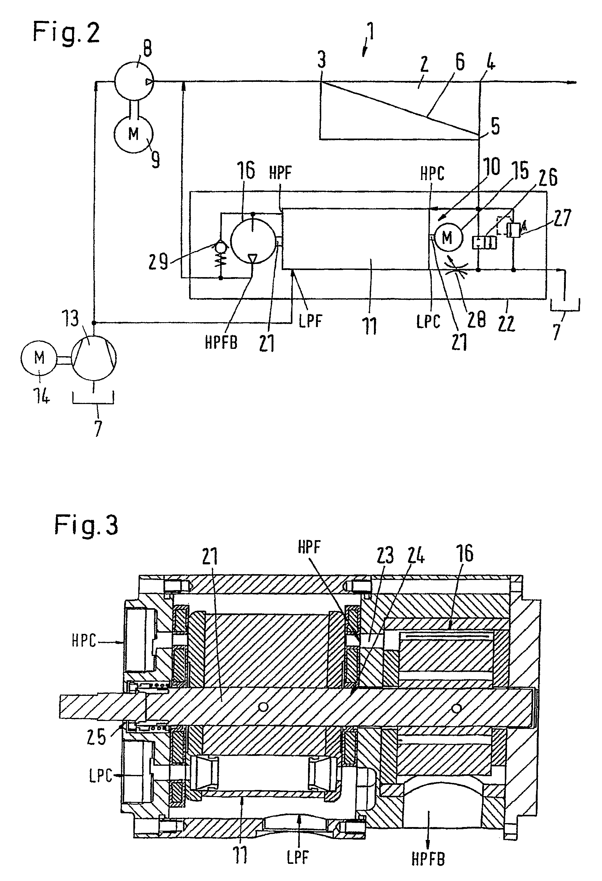
[0022]It is also preferred that a safety valve is arranged in parallel to the displacement pump. This safety valve prevents the pressure difference over the displacement pump from becoming too large.

Problems solved by technology

This may cause that the time available for a pressure exchange is too short.

Method used


Image

  • Reverse osmosis system
  • Reverse osmosis system
  • Reverse osmosis system

Examples


Embodiment Construction

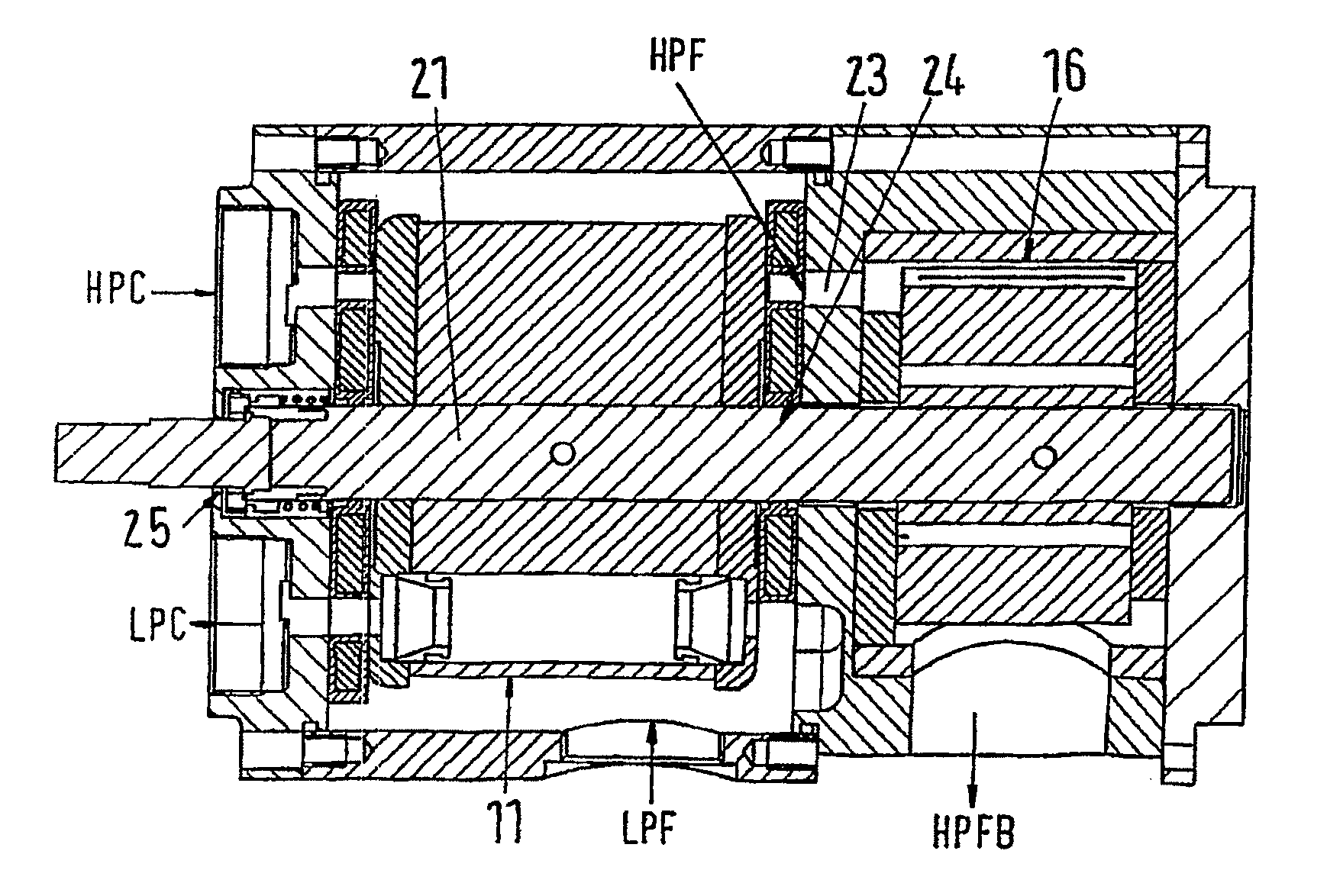
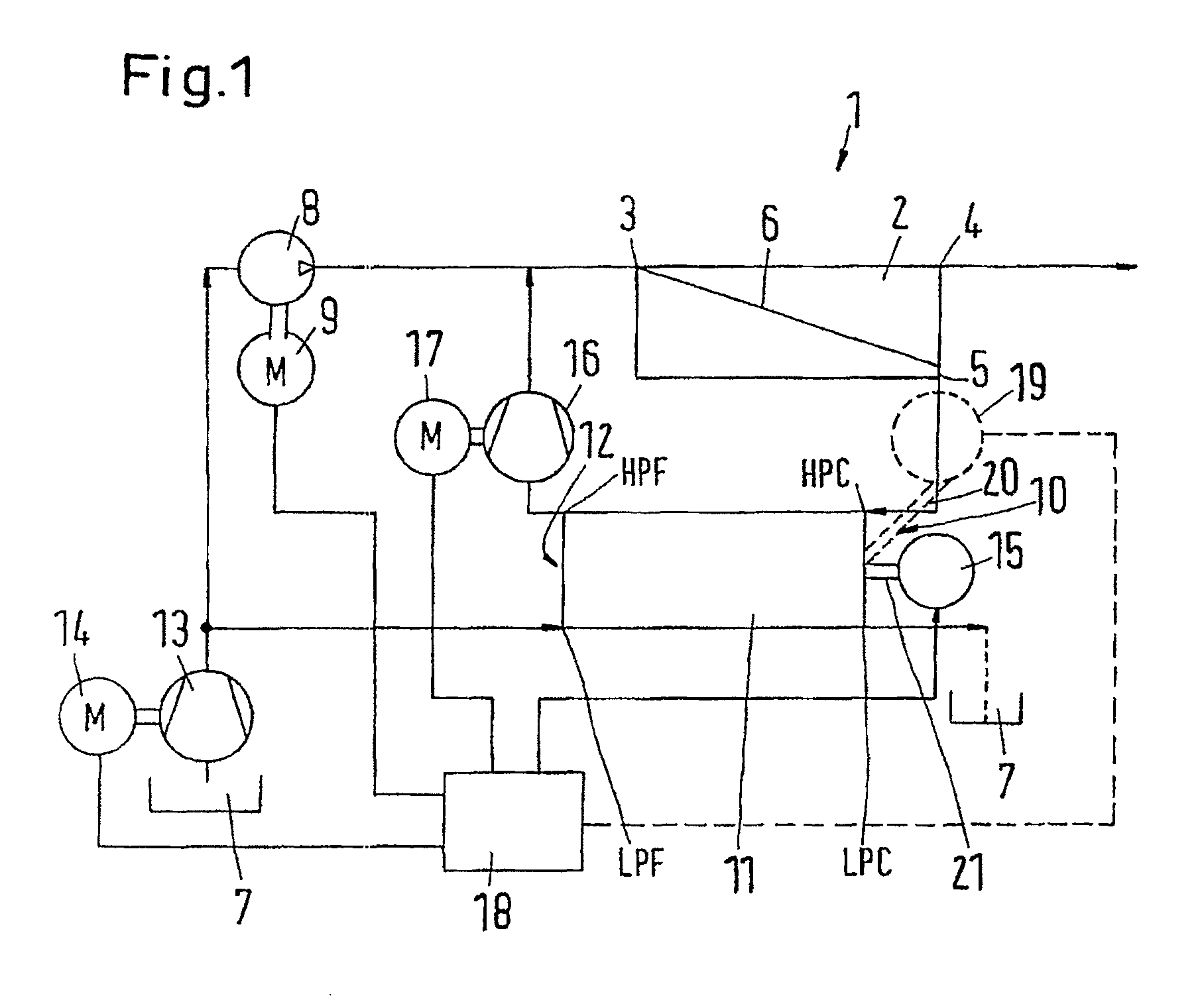
[0029]FIG. 1 is a schematic view of a reverse osmosis system 1, which can also be called a reverse osmosis plant or a reverse osmosis arrangement.

[0030]The reverse osmosis system comprises a membrane unit 2 with an inlet 3, a permeate outlet 4 and a concentrate outlet 5. A membrane 6 is arranged between the inlet 3 and the permeate outlet 4.

[0031]By means of a high-pressure pump 8, which is driven by a motor 9, the membrane unit 2 is supplied with feed water from a reservoir 7, for example, the sea. The high-pressure pump 8 can, for example, be a piston pump. The motor 9 can be an electric motor, which is controlled by a frequency converter. Thus, it is possible to drive the high-pressure pump 8 with variable speeds and thus variable outputs.

[0032]For reasons of simplicity, the water from the reservoir 7 will in the following be called “feed water”.

[0033]The concentrate outlet 5 is connected to a concentrate side 10 of a pressure exchanger 11, or rather, to a high-pressure concentra...


PUM


Abstract

The invention concerns a reverse osmosis system (1) with a membrane unit (2) comprising an inlet (3), a permeate outlet (4) and a concentrate outlet (5), a high-pressure pump (8) that is connected to the inlet (3), a pressure exchanger (11) connected on its concentrate side (10) to the concentrate outlet (5), and a booster pump between the pressure exchanger (11) and the inlet (3). It is endeavored to make the energy consumption as small as possible. For this purpose, the booster pump is made as a displacement pump.

Description

CROSS REFERENCE TO RELATED APPLICATIONS[0001]This application is entitled to the benefit of and incorporates by reference International Patent Application No. PCT / DK2009 / 000192 filed on Aug. 28, 2009 and German Patent Application No. 10 2008 044 869.9 filed on Aug. 29, 2008.FIELD OF THE INVENTION[0002]The invention concerns a reverse osmosis system with a membrane unit comprising an inlet, a permeate outlet and a concentrate outlet, a high-pressure pump that is connected to the inlet, a pressure exchanger connected on its concentrate side to the concentrate outlet, and a booster pump between the pressure exchanger and the inlet.BACKGROUND OF THE INVENTION[0003]A reverse osmosis system, for example, serves the purpose of gaining drinking water from salt water or waste water, in the following called “feed water”. For this purpose, the high-pressure pump brings the feed water to a relatively high pressure, for example 80 bar or more, after which the feed water is supplied to the membra...

Claims


Application Information

Patent Timeline
Patent Type & Authority Patents(United States)
IPC IPC(8): B01D61/02F04F13/00B01D61/06B01D61/10B01D61/12
CPCB01D61/025B01D61/06B01D61/10B01D61/12F04F13/00B01D2311/246B01D2313/246B01D2313/243Y02A20/131
Inventor FRIEDRICHSEN, WELMOLSEN, PALLEHAUGAARD, ERIK
Owner DANFOSS AS
Why Eureka
Eureka Blog
Learn More