Solar tunable filter assembly
a tunable filter and solar energy technology, applied in the field of tunable filters, can solve the problems of reducing the isolating effect, producing a spectral output with unwanted background signals that are also potentially dangerous to the human eye, and minimizing the degree of optical coupling. , to achieve the effect of minimizing the residual reflection and minimizing the degree of optical coupling
- Summary
- Abstract
- Description
- Claims
- Application Information
AI Technical Summary
Benefits of technology
Problems solved by technology
Method used
Image
Examples
embodiment 70
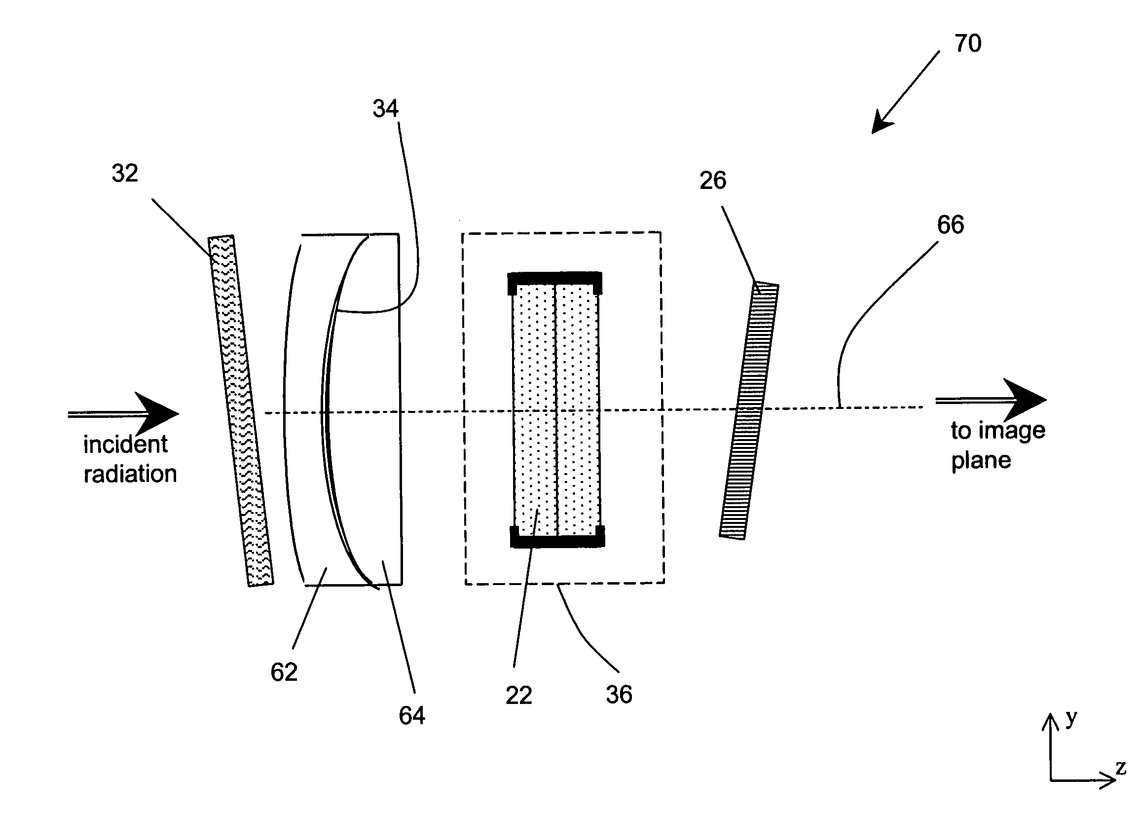
[0043]FIG. 8 illustrates an alternative embodiment 70 of the invention operating in transmission wherein the short-wave blocking component 32 of the ERF is placed in front of the collecting lenses 62,64, which serves the purpose of protecting the collecting optics and from UV exposure as well as from mechanical damage. The filter assembly 70 is otherwise the same as the embodiment of FIG. 7. FIG. 9 shows yet another embodiment 72 wherein the short-wave blocking component 32 of the ERF is formed as a thin-film filter on the front surface of the light collecting optics, while the long-wave blocking component 34 of the ERF is added as a separate filter positioned at the end of the filter train.
embodiment 74
[0044]FIG. 10 illustrates still another embodiment 74, wherein some filtering components (for example, the OSF 26 and the short-wave ERF component 32) are integrated with the conditioning optical components 76 of the system (such as a pentaprism, right-angle prism, or reflective mirror folding the optical path by 90°, as shown). This integration may be achieved in conventional manner by depositing thin-film filters on the surface of the conditioning optics.
[0045]FIG. 11 illustrates another embodiment 80 in which all filter components operate in transmission. Both the etalon 22 and the OSF 26 are traversed twice by an optical path that is folded toward the image plane first by conditioning optics 76 and then by a beam-splitter 82. This embodiment is used to increase the Finesse (spatial resolution) of the filter. Compared to a conventional two-etalon stack, this arrangement has the advantage of having the light pass through the same etalon, with the exact optical characteristics, twi...
embodiment 90
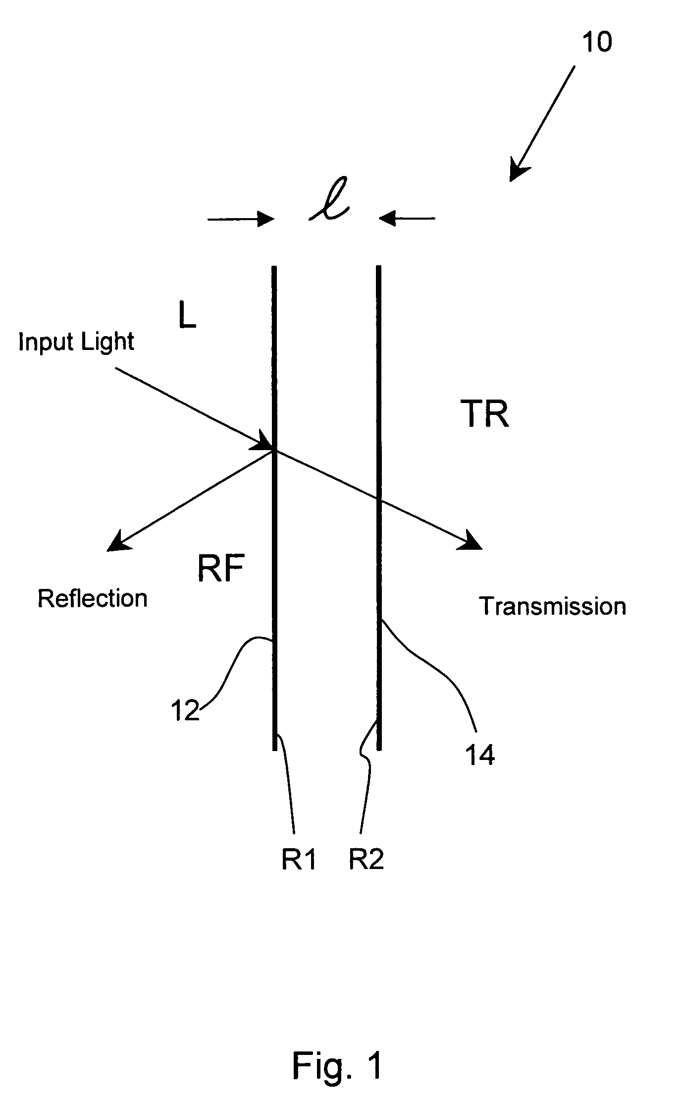
[0046]Finally, FIGS. 13 and 14 illustrate a preferred, actual embodiment 90 of the invention tuned by applying counterbalanced compressive forces on a conventional etalon 22 to vary in very precise fashion the optical length of its cavity, as fully disclosed in Ser. No. 10 / 795,167. The optical length of the etalon is determined by the thickness of its spacers (see FIG. 1) which separate the optical surfaces of the cavity by exerting the force necessary to keep them apart at a predetermined distance. On the other hand, all spacer materials are characterized by a certain degree of resilience (within the Young's Modulus limits of the material) which affords an opportunity to change the thickness of the spacers by applying a controlled compressive force over them.
[0047]Accordingly, as shown in the exploded view of FIG. 13, a conventional etalon 22 is mounted inside a cylindrical main cell 86 butting against an appropriately formatted recess 88. A tuning cell 92, positioned over the etal...
PUM
 Abstract
Description
Claims
Application Information
 - R&D
- Intellectual Property
- Life Sciences
- Materials
- Tech Scout
- Unparalleled Data Quality
- Higher Quality Content
- 60% Fewer Hallucinations
Browse by: Latest US Patents, China's latest patents, Technical Efficacy Thesaurus, Application Domain, Technology Topic, Popular Technical Reports.
© 2025 PatSnap. All rights reserved.Legal|Privacy policy|Modern Slavery Act Transparency Statement|Sitemap|About US| Contact US: help@patsnap.com


