
Battery pack with thermal distribution configuration

a battery pack and thermal distribution technology, applied in the field of rechargeable batteries, can solve the problems of increasing the number of cells b, increasing the temperature differential between, and increasing the number of cells

Inactive Publication Date: 2006-12-12
PANASONIC CORP +1
View PDF48 Cites 21 Cited by
  • Summary
  • Abstract
  • Description
  • Claims
  • Application Information

AI Technical Summary

Benefits of technology

[0011]With the structure of this rechargeable battery, the plurality of cells that make up the battery pack are arranged in a single row with the short sides of the battery housings next to each other, so the long sides of the cells all face outward and the temperature environment thereof is equalized, resulting in an extremely small temperature differential between the cells. Therefore, there is also less difference in charging efficiency, which varies with the battery temperature, and there is no variance in the cell capacity, so none of the cells is overdischarged during discharging, and the cycling life of the rechargeable battery can be kept long.
[0013]With the structure of this rechargeable battery, the plurality of cells that make up the battery pack are arranged in a single row with the short sides of the battery housings next to each other, thus forming a battery module, and these battery modules are arranged in parallel in a plurality of rows, so the long sides of the cells face outward and the temperature environment is equalized, resulting in an extremely small temperature differential between the cells. Therefore, there is also less difference in charging efficiency, which varies with the battery temperature, and there is no variance in the cell capacity, so none of the cells is overdischarged during discharging, and the cycling life of the rechargeable battery can be kept long. It is also possible to increase the number of battery modules linked or shorten the linkage length by further disposing in parallel battery modules linked on the short sides.
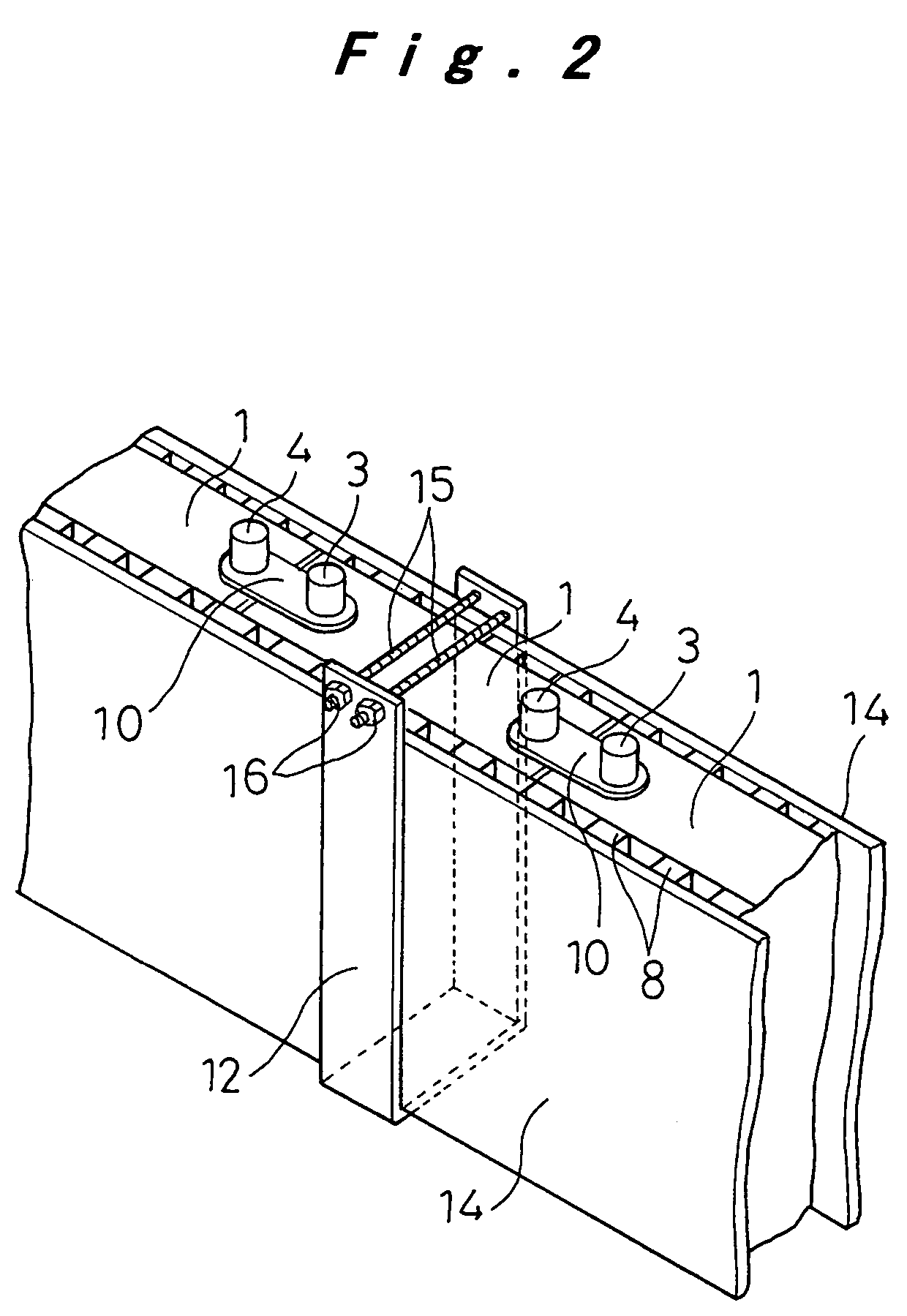
[0014]In the above structure, if a heat transfer plate with good thermal conductivity is provided between the battery modules disposed in parallel, then the heat between the sides facing each other in parallel, where the long sides of the battery housings are next to each other and heat radiation is not as good, can be exchanged to the heat transfer plate, and the temperature can be kept from rising between sides facing each other in parallel where heat radiation is not as good.
[0016]Active cooling via a heat exchanger is also possible by making a coolant flow through the heat transfer plate and / or the end heat transfer plates, which allows the various battery modules to be maintained at the optimal temperature.
[0017]If a plurality of cells are linked together with the elements for electromotive force of each cell provided inside a battery case in which the individual battery housings are integrally formed adjacent to one another between the short sides thereof, then the plurality of cells will be integrally structured such that the battery case common to the plurality of cells serves as the battery housings of the various cells, so the structure linking the battery housings can be formed more easily.
[0020]A plurality of ribs can also be formed on the sides of the battery housings, and a coolant made to flow through the spaces formed between the ribs. Coolant passages are formed between the ribs by contact between the ribs and the binding plates or between the ribs of adjacent battery housings or case, and the heat radiation of the various cells can be effectively achieved by making a coolant flow through these coolant passages.

Problems solved by technology

Nevertheless, when a battery pack is produced by arranging cells as in this conventional structure, a problem is that the greater is the number of cells 1 arranged, the greater is the temperature differential between the cells 1 located toward the middle and the cells 1 located on the outer ends.
The closer a cell 1 is to the middle, the more it is affected by the heat generated by the cells 1 to either side, so the temperature rises more and heat radiation is not as good.
Repeated charging and discharging in this state in which there is a difference in the capacity of the cells shortens the cycling life of a battery pack and leads to diminished dischargeable capacity.

Method used


Image

  • Battery pack with thermal distribution configuration
  • Battery pack with thermal distribution configuration
  • Battery pack with thermal distribution configuration

Examples


first embodiment

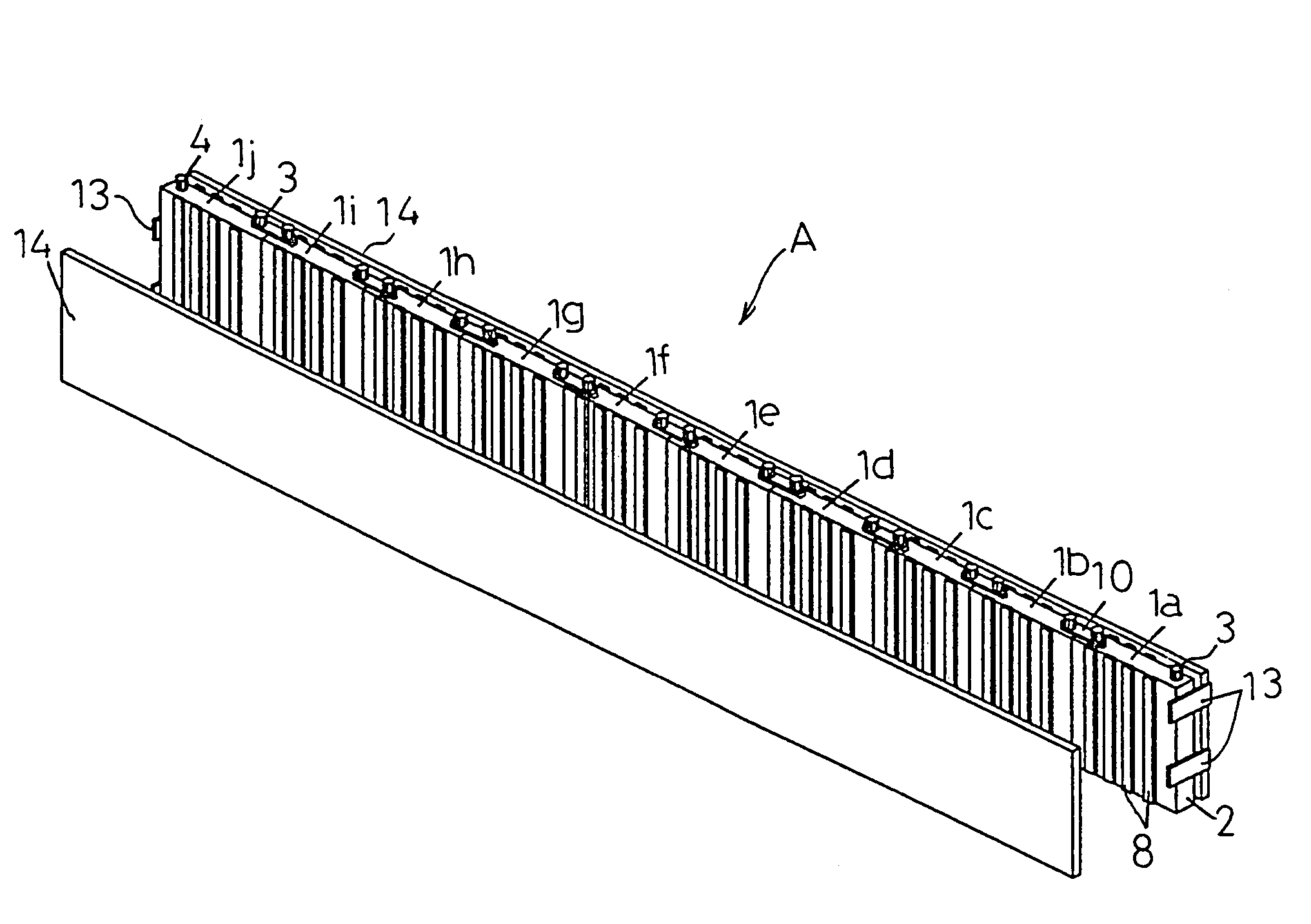
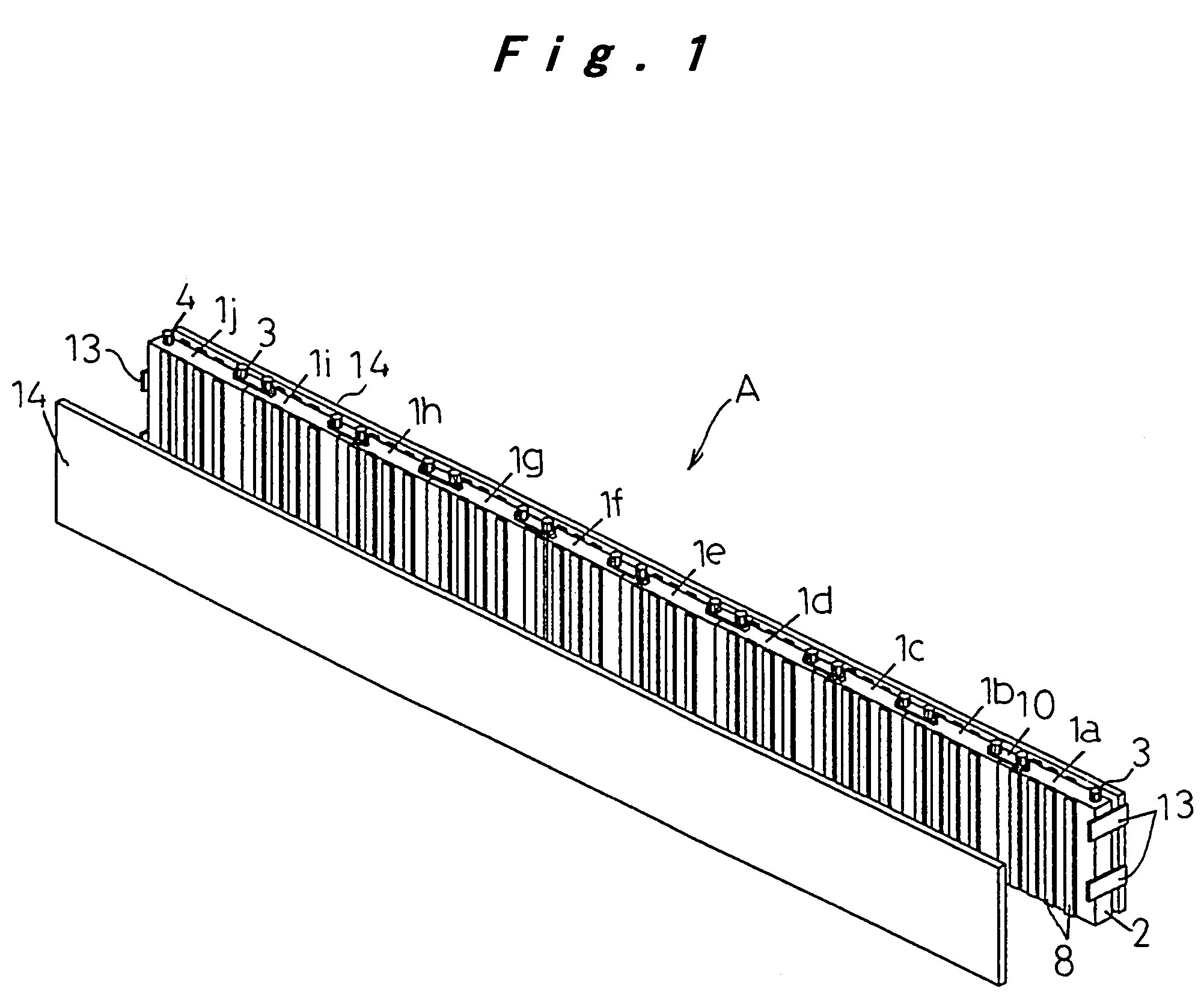
[0039]In FIG. 1, the rechargeable battery A pertaining to the first embodiment is structured such that ten cells 1a to 1j that are nickel metal-hybrid rechargeable cells are linked together, and the positive and negative electrode terminals 3 and 4 of the cells 1a to 1j are connected in series to form a battery pack that provides the required output voltage. The cells 1a to 1j are arranged in a chain, with the short (narrow) sides of the battery housings 2 (each of which is formed in a rectangular shape) abutted against one another. These are integrally linked together by being sandwiched between binding plates 14 on the long (wide) sides of the battery housings 2. The two binding plates 14 are fixed by being tightly fitted between binding bands 13 at the ends, as shown in the figure.

[0040]If a large number of cells 1 are to be linked up, tightly fitting the ends of the long binding plates 14 between the binding bands 13 can result in bulging in the middle portion if the binding pla...

fifth embodiment

[0055]FIG. 11 illustrates the structure of a rechargeable battery E pertaining to the Rechargeable battery E is structured such that a battery module 38a, comprising five cells 21a to 21e integrally connected by battery cases 36 provided with partitions 18, and a battery module 38b, comprising five similarly integrally connected cells 21f to 21j are butted together in parallel rows, binding plates 24 are butted against the outsides of the grouped batteries 38a and 38b, and the ends of these binding plates 24 are bound and fixed by binding bands 25.

sixth embodiment

[0056]FIG. 12 illustrates the structure of a rechargeable battery F pertaining to the Rechargeable battery F is structured such that a battery module 38a, comprising five cells 21a to 21e integrally connected by battery cases 36 provided with partitions 18, and a battery module 38b, comprising five similarly integrally connected cells 21f to 21j are butted together in parallel rows with the heat transfer plate 30 sandwiched in between, the ends of this heat transfer plate 30 are linked by the end heat transfer plates 29, the binding plates 24 are butted against the outsides of the grouped batteries 38a and 38b, and the ends of these binding plates 24 are bound and fixed by binding bands 35.

[0057]The heat radiation action and effect of these rechargeable batteries E and F are the same as with the structures described above for the third and fourth embodiments, and therefore will not be described again, but the difference from prior art will be illustrated through the following test ...


PUM


Abstract

A plurality of cells (1a to 1j) are abutted against each other and electrically connected on the short sides of rectangular battery housings (2), and binding plates (14, 14) disposed on both long sides are tied together with binding bands (13) to integrally link the cells (1a to 1j). Because the heat radiation conditions are equalized among the cells (1a to 1j), there is an extremely small temperature differential between the cells, charging efficiency, which varies with temperature conditions, is consistent, and there is no variance in battery capacity, so none of the cells are over-discharged, and battery life is extended.

Description

REFERENCE TO RELATED APPLICATION[0001]This is a continuation application of and incorporates the entire disclosure of application Ser. No. 09 / 856,608 filed Jun. 27, 2001, issued as U.S. Pat. No. 6,818,343 on Nov. 16, 2004.TECHNICAL FIELD[0002]The present invention relates to a rechargeable battery configured in the form of a battery pack in which a plurality of cells are connected so as to obtain the required electrical capacity, and more particularly to a rechargeable battery in which the heat radiation of the battery pack is enhanced and there is less temperature differential between cells, so that charging efficiency is equalized and there is no variance in the battery capacity of the various cells.BACKGROUND ART[0003]A conventional rechargeable battery constructed such that the required electrical capacity is obtained by connecting and integrally linking a plurality of cells into a battery pack is structured as shown in FIG. 16, for example. This rechargeable battery is an examp...

Claims


Application Information

Patent Timeline
IPC IPC(8): H01M2/10H01M10/50H01M2/00H01M10/60H01M10/613H01M10/647H01M10/6555H01M10/6557H01M10/6563H01M50/209H01M50/264H01M50/289H01M50/51H02J7/04
CPCH01M2/1016H01M2/1022H01M2/1077H01M2/202H01M10/5004H01M10/5032H01M10/5046H01M10/5059H01M10/5065H01M10/647H01M10/6551H01M10/6557H01M10/613H01M10/6562Y02E60/10H01M50/209H01M50/51H01M50/264H01M50/289
Inventor KIMOTO, SHINYATAKAKI, MITSUGUKIMURA, KENJIYOKOYAMA, TOSHINOBUFUKUDA, SHINSUKETAKAHASHI, YASUHIROKATSUTA, TOSHIHIROASAKAWA, KIEKO
Owner PANASONIC CORP
Learn More