Power transmission device

a transmission device and power technology, applied in the direction of gearing, oblique crank gearing, hoisting equipment, etc., can solve the problems of low transmission efficiency, high cost, and large energy loss of the transmitting mechanism using worm gears, and achieve high rotation efficiency, high self-locking function, and high reduction ratio

Inactive Publication Date: 2006-12-12
SUMITOMO HEAVY IND LTD
View PDF5 Cites 12 Cited by
  • Summary
  • Abstract
  • Description
  • Claims
  • Application Information

AI Technical Summary

Benefits of technology

[0021]For example, in order to allow a self-locking function during stopping to coexist with rotational smoothness during operation, the possibility that the high self-locking function can be secured must be created depending on a design, and the possibility that high rotation efficiency can be achieved must be created depending on a design. The present invention adopts the internally meshing planetary gear mechanism, and therefore, can obtain a high reduction ratio by one stage and can obtain high rotation efficiency by reducing the frictional resistance of each sliding portion. On the other hand, a design can be prepared so that the high self-locking functionality can be obtained by raising the frictional resistance of each sliding portion or by lowering the rigidity of some materials. The characteristics of low noise and slight vibrations originally appear when a light load is applied, and backlash is also small. Especially, if a design is made so that each member can be easily deformed by positively lowering the rigidity as described later, a state where backlash is almost zero (0) can also be easily created. Since a design to enlarge backlash can be easily prepared, the backlash can be desirably and easily enlarged or reduced according to the design. Additionally, the mechanism has great design freedom to adjust the number of internal and external teeth meshing together that contribute to power transmission or a contact area between the internal and external contacting tooth surface, and the transmission capacity thereof can also be easily controlled and adjusted.
[0022]In the present invention, internally meshing planetary gear mechanisms are characterized by being high in basic performance, by being flexible in design, and by undergoing a marked change in the effects obtained with respect to a design change as described above, and are disposed in parallel on a path of power transmission. In the thus constructed mechanisms, predetermined functions are intentionally distributed by creating a difference in power transmission characteristics in each system. Therefore, a design can be made so that a specific system contributes to power transmission more positively when a predetermined condition is satisfied. As a result, conflicting requirements can coexist together rationally and effectively.

Problems solved by technology

However, a problem resides in the fact that a special mechanism to fulfill the backstop function is needed separately from the device body, and therefore the device will be enlarged or costs will be raised.
However, a problem resides in the fact that the transmitting mechanism that uses worm gears has low transmission efficiency and great energy loss (i.e., great power consumption).
Generally, a power-transmitting mechanism having the self-locking function has low transmission efficiency without being limited to the transmitting mechanism that uses worm gears.
Therefore, power consumption becomes higher correspondingly therewith.
Besides this, design requirements in conflict with each other exist between high torque and high transmission capacity both of which are needed when activated or when accelerated (i.e., when heavily loaded) and low noise and less vibration both of which are needed when steadily operated (i.e., when lightly loaded).
However, if so, the device will become more complex, and costs will be inevitably raised.

Method used


Image

  • Power transmission device
  • Power transmission device
  • Power transmission device

Examples


Embodiment Construction

[0042]Embodiments of the present invention will be hereinafter described with reference to the drawings.

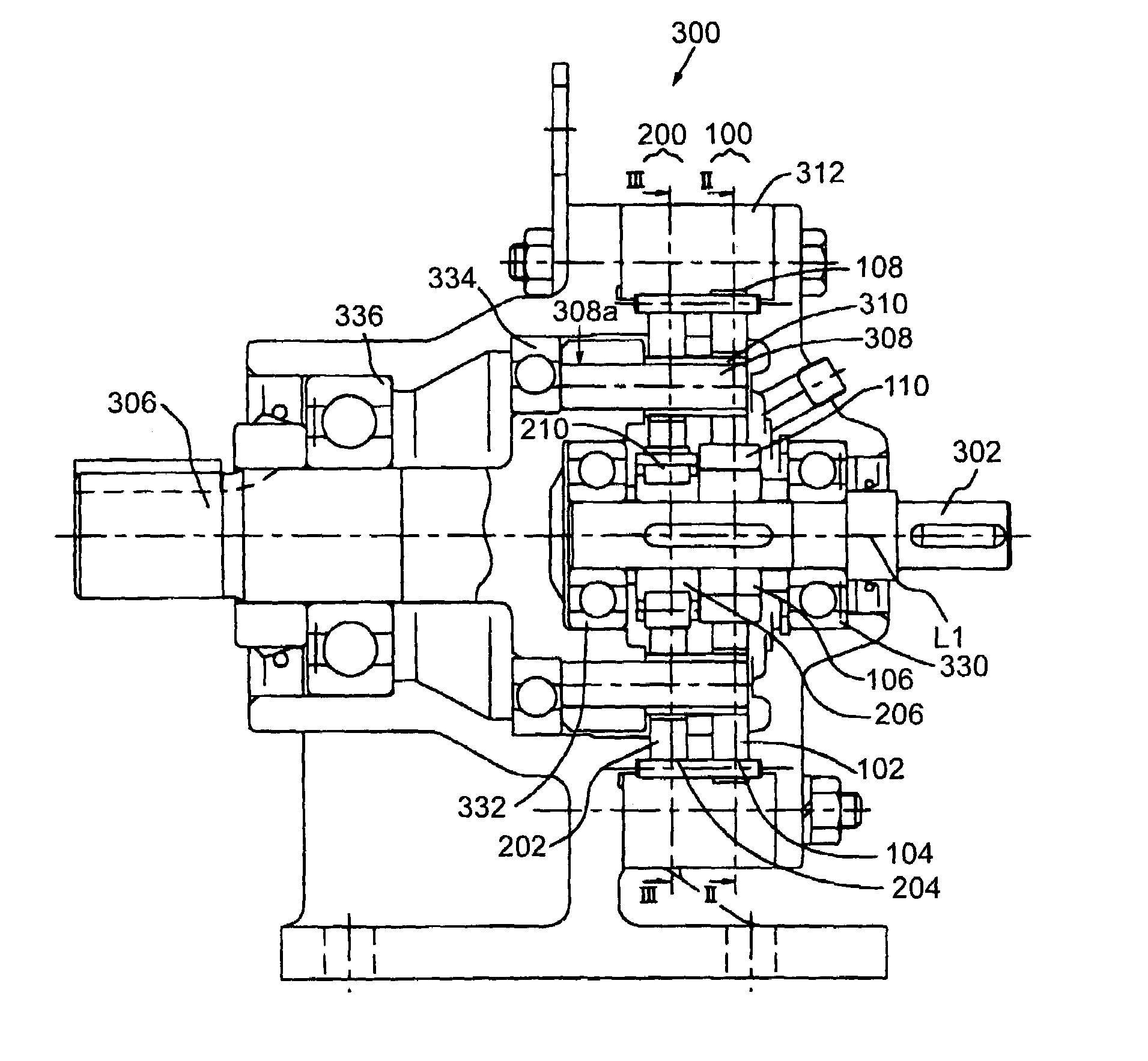
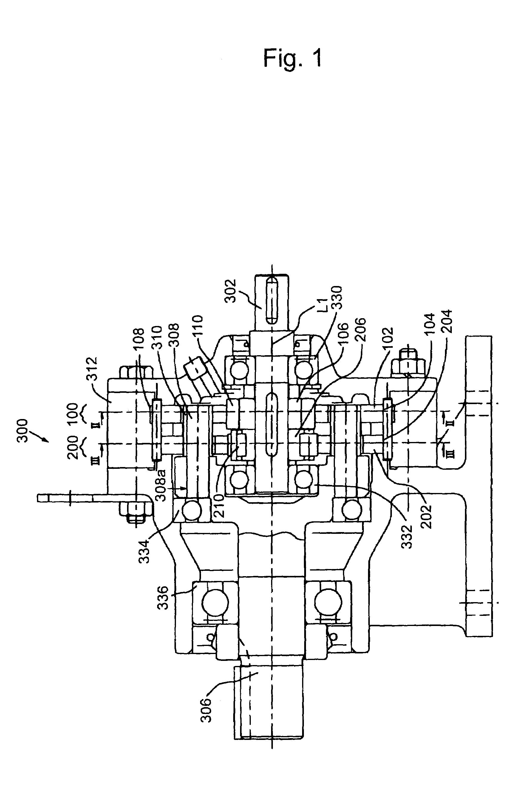
[0043]FIG. 1 is a sectional side view of a power transmission device 300 according to an embodiment of the present invention.

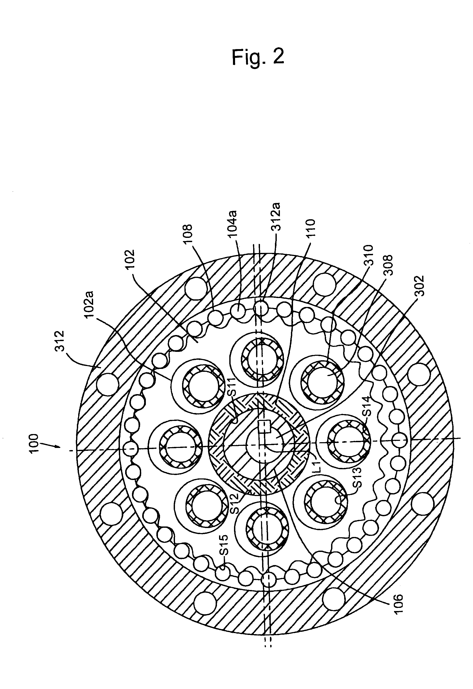
[0044]The power transmission device 300 includes an input shaft 302, an output shaft 306, a first internally meshing planetary gear mechanism 100 which is a first power-transmitting mechanism, and a second internally meshing planetary gear mechanism 200 which is a second power-transmitting mechanism. The power transmission device 300 can transmit power inputted from the input shaft 302 to a mating apparatus (driven apparatus), not shown, through the first and second internally meshing planetary gear mechanisms 100 and 200 and the output shaft 306.

[0045]The input shaft 302 is rotatably supported at both its ends by bearings 330 and 332, and can rotate around an axial center L1.

[0046]The output shaft 306 is rotatably supported by bearings 334 and 336, and can ...


PUM


Abstract

It is an object to obtain a power transmission device capable of allowing conflicting needs to coexist rationally and effectively in accordance with a driving situation. As powertransmitting mechanisms of a power transmission device, there are provided a plurality of characteristically-differentiated internally meshing planetary gear mechanisms, each having an external gear and an internal gear having external teeth and internal teeth the difference in the number of teeth between which is slight. In this structure, at least two of the internally meshing planetary gear mechanisms are disposed in parallel on a path of power transmission, and power transmission characteristics of the two mechanisms are designed to differ from each other.

Description

BACKGROUND OF THE INVENTION[0001]1. Field of the Invention[0002]This invention relates to a power transmission device.[0003]2. Description of the Related Art[0004]When various mechanical apparatuses (driven apparatuses), such as conveyers, joints of industrial-use robots, and elevators, are driven, a power transmission device is interposed between a driving source and the mechanical apparatuses. The power transmission device is used to diminish the rotational speed of power outputted from the driving source, to increase the torque, or to change the axial direction of rotation. An internally meshing planetary gear mechanism is known as a structure forming the power transmission device. The internally meshing planetary gear mechanism includes external gears and internal gears between which a difference in the number of teeth is slight.[0005]As a concrete structure of the internally meshing planetary gear mechanism, proposals have been made of an oscillating internally-meshing structur...

Claims


Application Information

Patent Timeline
Patent Type & Authority Patents(United States)
IPC IPC(8): F16H23/00F16H1/32F16H3/70F16H55/24
CPCF16H1/32F16H55/24
Inventor MINGISHI, KIYOJITAMENAGA, JUNYAMANAKA, TEIJIROUSHIMADA, MASAHIRO
Owner SUMITOMO HEAVY IND LTD
Why Eureka
Try Eureka