
Heat dissipation device

a heat dissipation device and electronic component technology, applied in the direction of power cables, semiconductor/solid-state device details, cables, etc., can solve the problems of deteriorating operational stability, damage to associated electronic devices, and large heat generation of electronic devices such as central processing units (cpus)

Inactive Publication Date: 2006-11-28
HON HAI PRECISION IND CO LTD +1
View PDF14 Cites 67 Cited by
  • Summary
  • Abstract
  • Description
  • Claims
  • Application Information

AI Technical Summary

Benefits of technology

The present invention provides a heat dissipation device that efficiently dissipates heat from an electronic component without wasting space on the printed circuit board. The device includes a mounting plate, heat sink, core, and fan. The mounting plate is spaced from the circuit board to allow the capacitors to locate between the mounting plate and the circuit board. The mounting plate defines a plurality of openings for providing access for cooled air from the fan to the heat generating component. The technical effects of the invention are improved heat dissipation efficiency and reduced space usage.

Problems solved by technology

Electronic devices such as central processing units (CPUs) generate a lot of heat during normal operation.
This can deteriorate their operational stability and damage associated electronic devices.
However, this kind of base is prone to interfere with other electronic components of a printed circuit board around the CPU since the base is close to the printed circuit board.
Thus, the other electronic components must be removed away from the base to another location on the printed circuit board, thereby wasting space of the printed circuit board under the base.
The other area of the base is far from the CPU and cannot efficiently transfer heat from the CPU to the fins.

Method used


Image

  • Heat dissipation device
  • Heat dissipation device
  • Heat dissipation device

Examples


Embodiment Construction

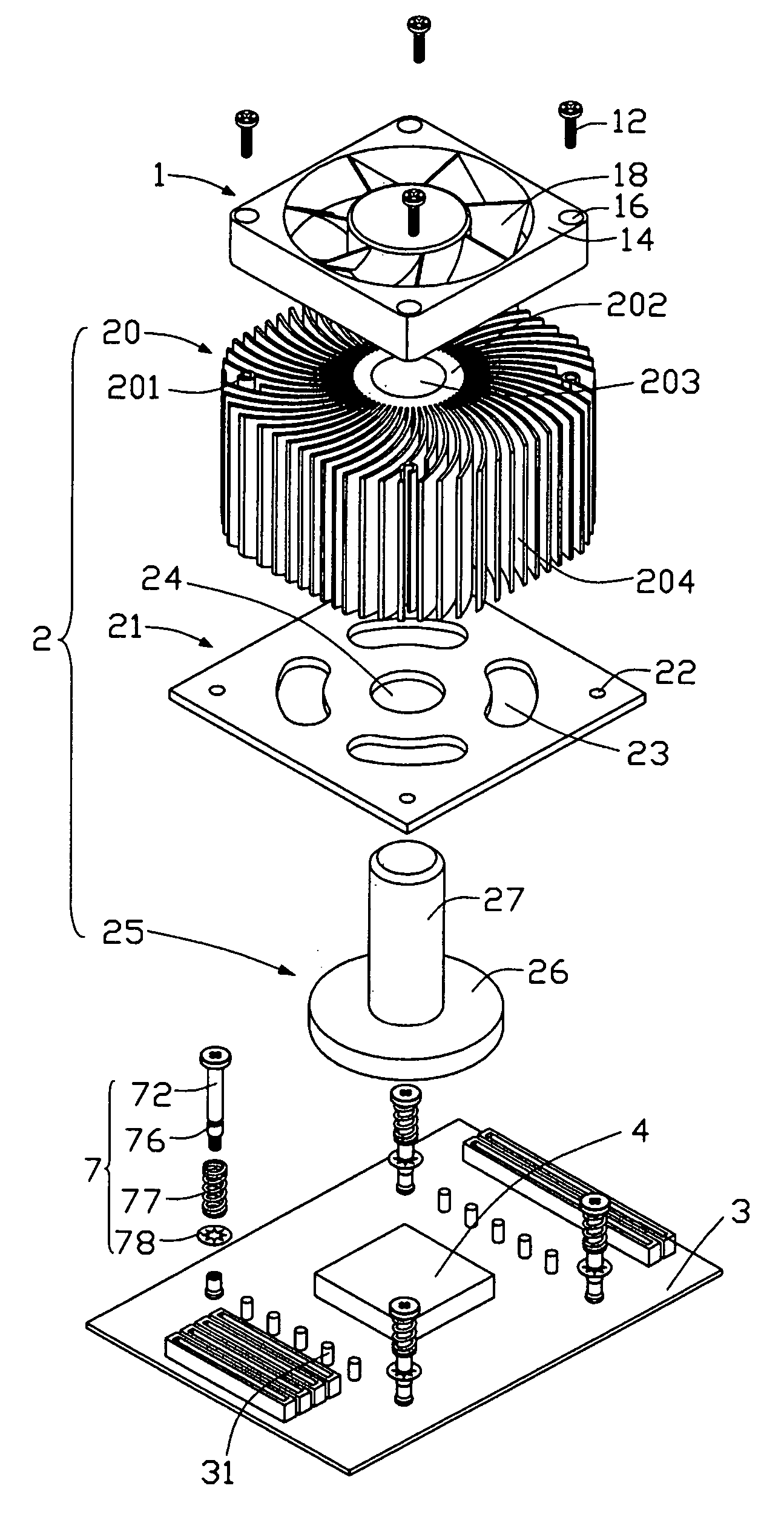
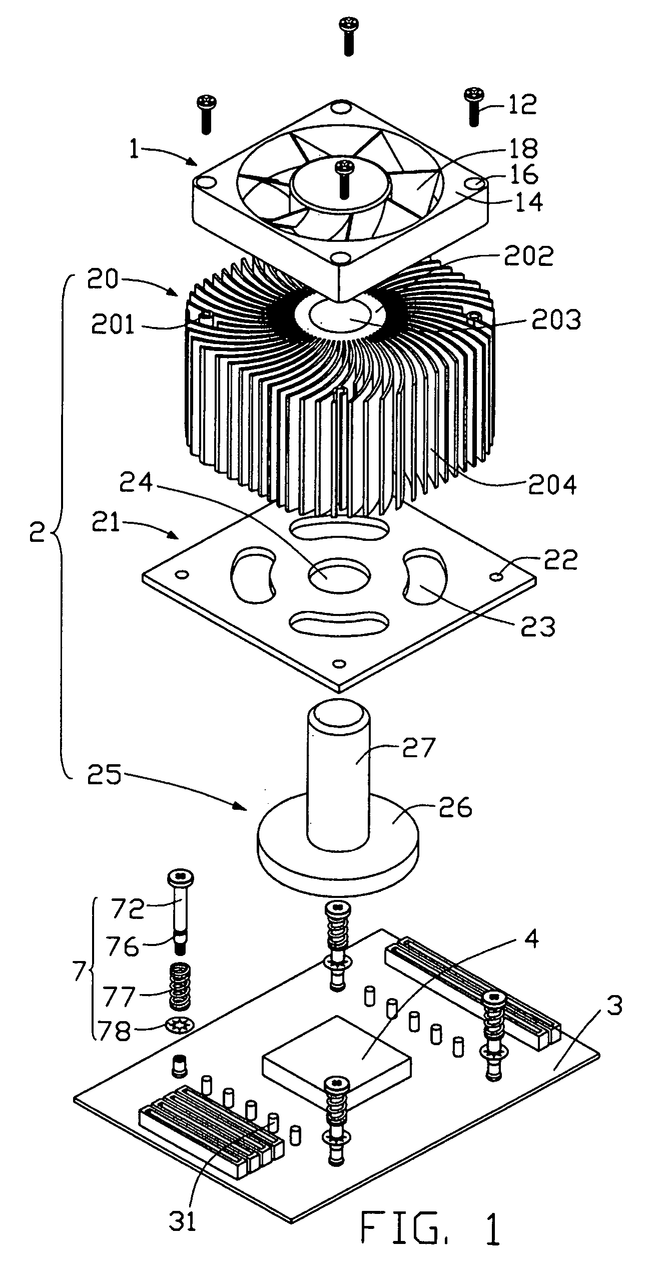
[0013]Referring to FIGS. 1 and 2, a heat dissipation device in accordance with the preferred embodiment of the present invention comprises a fan 1, a radiator 2, a back plate 6 and a plurality of fasteners 7. The fan 1 is for being attached on the radiator 2 and comprises a rectangular frame 14 and a plurality of vanes 18 installed in a central opening of the frame 14. The frame 14 defines four through holes 16 in four corners thereof.

[0014]The radiator 2 comprises a heat sink 20, a rectangular mounting plate 21, and a core 25. The heat sink 20 comprises a central cylinder 202 defining a through aperture 203 therein, and a plurality of spaced curviform fins 204 extending radially from the cylinder 202. Four screw holes 201 are defined in free ends of four fins 204 for engaging with four screws 12 which extend through the through holes 16 of the fan 1, respectively. The mounting plate 21 defines a through aperture 24 in a center thereof, and four through openings 23 surrounding the t...


PUM


Abstract

A heat dissipation device includes a mounting plate (21) for mounting the heat dissipation device to a circuit board (3) on which a CPU (4) and a plurality of capacitors (31) are mounted, a heat sink (20), a core (25), and a fan (1) mounted on the heat sink. The heat sink locates above the mounting plate and includes a hollow cylinder (202) and a plurality of curved fins (204) extending outwardly from the cylinder. The core includes a base (26) for contacting the CPU and a post (27) extending from the base through the mounting plate to be received in the cylinder. The mounting plate is spaced from the circuit board to allow the capacitors to locate between the mounting plate and the circuit board. The mounting plate defines a plurality of openings (23) for providing access for cooled air from the fan to the CPU and the capacitors.

Description

BACKGROUND OF THE INVENTION[0001]1. Field of the Invention[0002]The present invention relates to a heat dissipation device for electronic components, and particularly to a heat dissipation device for a central processing unit with a plurality of electronic components located therearound.[0003]2. Related Art[0004]Electronic devices such as central processing units (CPUs) generate a lot of heat during normal operation. This can deteriorate their operational stability and damage associated electronic devices. Thus the heat must be removed quickly to ensure normal operation. A heat dissipation device is often attached to a top surface of a CPU, to remove heat therefrom.[0005]A conventional heat dissipation device comprises a rectangular base and a plurality fins arranged on the base. The base is made of copper and the fins are made of aluminium. The base is used to contact a CPU for transferring heat from the CPU to the fins. A fan is often attached on the heat sink for enhancing heat d...

Claims


Application Information

Patent Timeline
Patent Type & Authority Patents(United States)
IPC IPC(8): H05K7/20G06F1/20H01L23/40H01L23/467
CPCH01L23/4006H01L23/467H01L2924/0002H01L2924/00
Inventor LEE, HSIEH KUNXIA, WAN-LINLIU, HE-BEN
Owner HON HAI PRECISION IND CO LTD
Learn More