
Data transmission method, data transmission system, transmitter and receiver

a data transmission system and data transmission technology, applied in the field of data transmission methods, data transmission systems, transmitters and receivers, can solve problems such as hardware scale of the memory, difficult for the receiving side to reproduce transmission data correctly, and inability to judge the effective data length of the received frame, so as to reduce overhead

Active Publication Date: 2006-11-21
NTT DOCOMO INC
View PDF18 Cites 18 Cited by
  • Summary
  • Abstract
  • Description
  • Claims
  • Application Information

AI Technical Summary

Benefits of technology

The present invention provides a method for transmitting data using a fixed time length frame with high-quality variable-rate data detection. The method involves calculating an error-detecting code for each frame and transmitting the frame with the calculated error-detecting code only if there is transmission data. The method also includes generating frame data containing the transmission data and the calculated error-detecting code, assuming a final bit position of the frame data where the error-detecting code matches the transmission data. The method reduces overhead by not transmitting unnecessary data and optimizes error detection. Additionally, the method allows for the efficient use of interleaving and error-correcting coding to improve data transmission quality.

Problems solved by technology

In addition, in the method where the receiving side determines the rate by using the error-detecting code that is added to the transmission data to indicate the transmission quality without sending any rate information, a decision error rate in determining the rate depends on a word length of the error-detecting code and doesn't decrease below a certain rate-decision error rate (namely, a probability of determining that no transmission error exists for an erroneous rate) even if the transmission error goes down.
On the other hand, in the case where the rate information is sent from the transmitting side to the receiving side, if an error occurs during transmission, an effective data length in the received frame cannot be judged and it becomes difficult for the receiving side to reproduce the transmission data correctly even if no error occurs in the data part.
Such buffer memory becomes large in size in proportion to the number of the transmission data bits of one frame, and when a huge amount of the transmission data is sent, hardware scale of the memory presents a problem.

Method used


Image

  • Data transmission method, data transmission system, transmitter and receiver
  • Data transmission method, data transmission system, transmitter and receiver
  • Data transmission method, data transmission system, transmitter and receiver

Examples


first embodiment

(First Embodiment)

[0064]FIGS. 3A and 3B show examples of block constructs of a transmitter and a receiver in a first embodiment of the present invention.

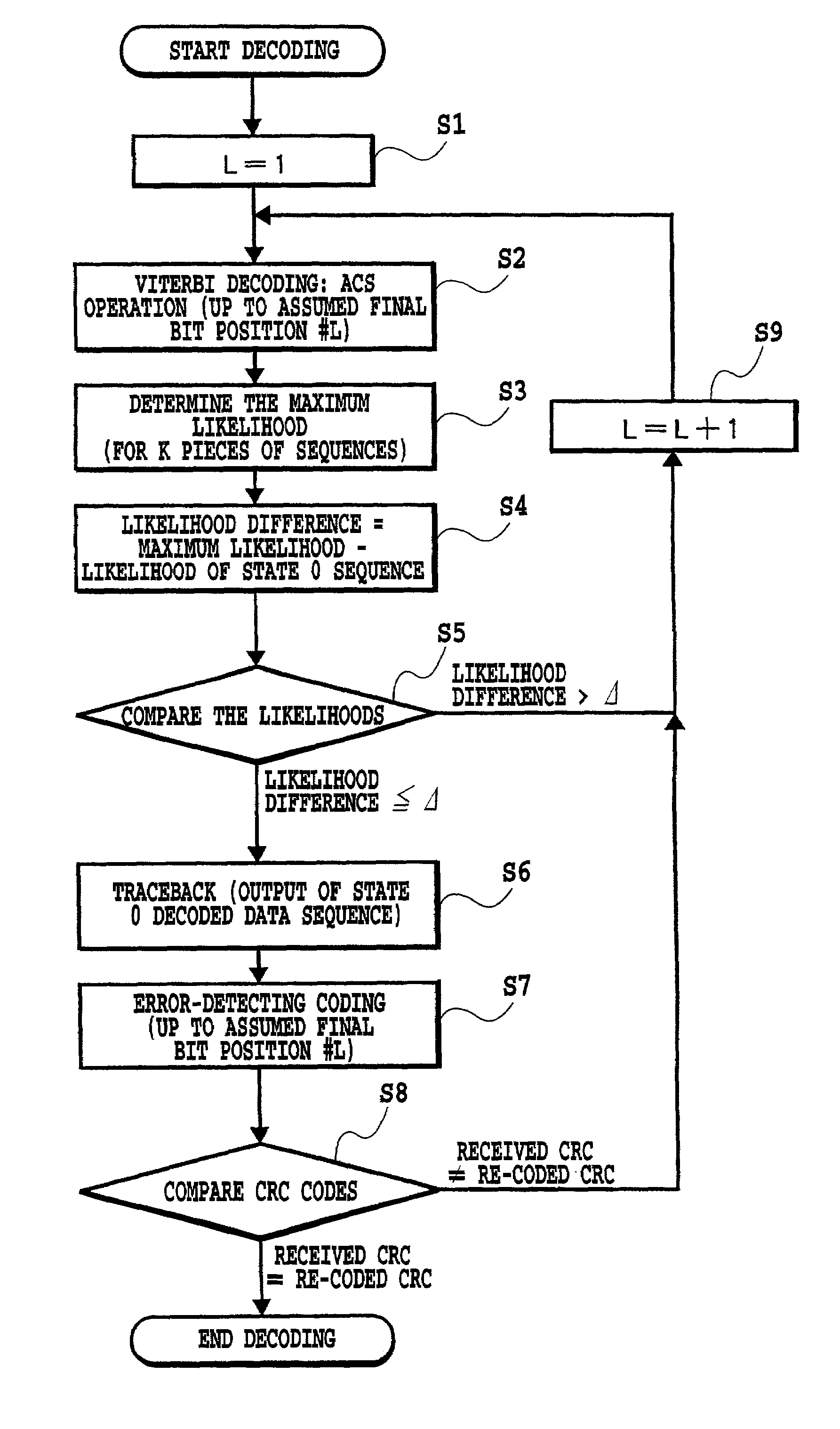
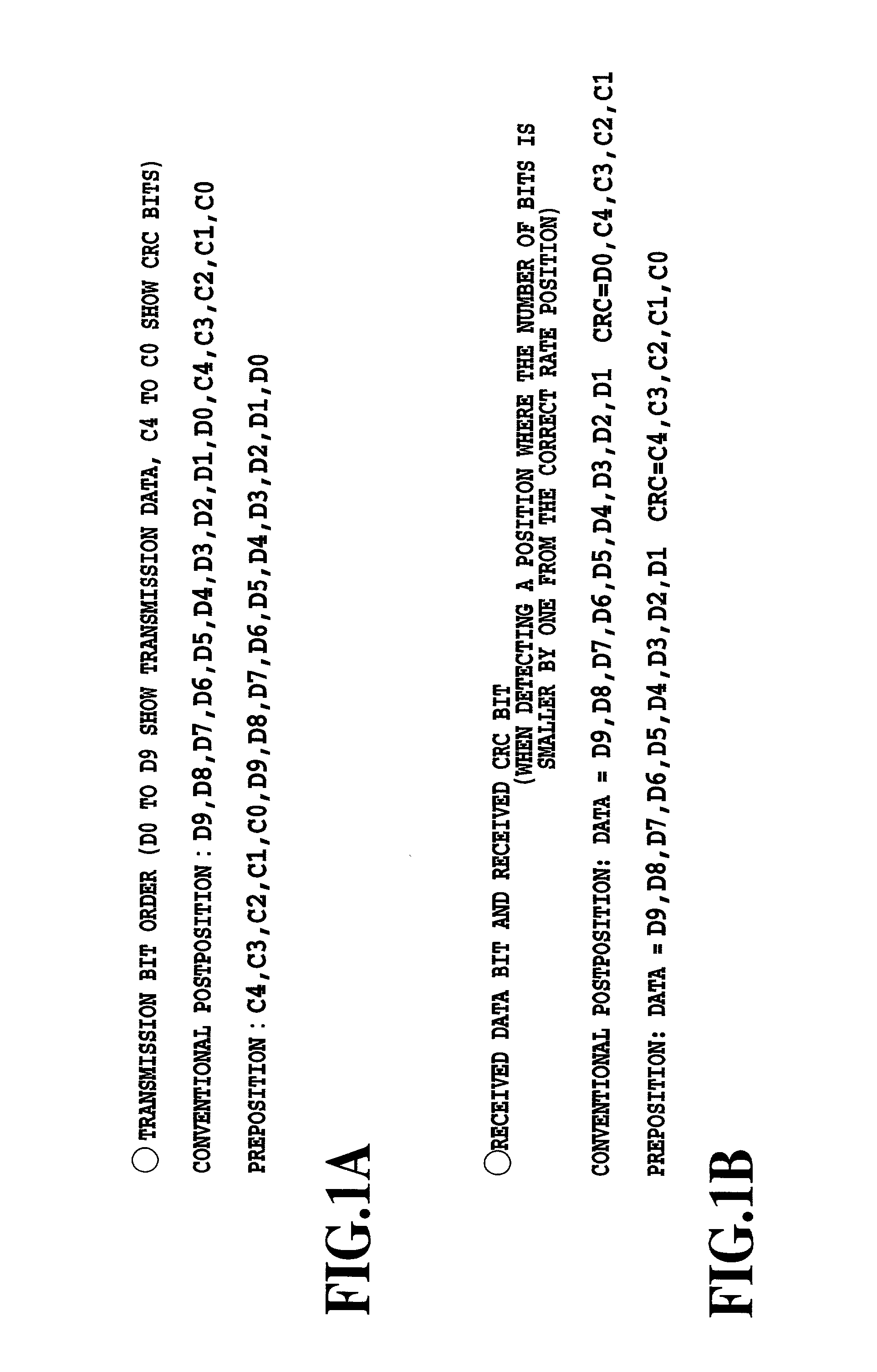
[0065]In FIGS. 3A and 3B, a transmission data sequence applied to a terminal 1 is sent both to an error-detecting coder 4 and a multiplexer 6. The error-detecting coder 4 calculates an error-detecting code (CRC parity bits (CRC bits) in this embodiment) for one frame of transmission data only if the frame contains the transmission data. In this embodiment, the word length of the CRC bits is a fixed length.

[0066]In this embodiment, the sum of the length of the transmission data and the length of the error-detection code (CRC bits) in one frame is 4096 bits maximum. The length of the error-detecting code is 16 bits. Thus, the length of the transmission data is 0 (when there is no data) or a value in the range from 1 to 4080 bits. According to this embodiment, the error-detecting code is not sent when there is no transmission data to r...

second embodiment

(Second Embodiment)

[0100]FIGS. 10A and 10B show examples of the block constructs of a transmitter and a receiver in a second embodiment according to the present invention.

[0101]In the configuration of FIGS. 10A and 10B, transmission of information indicating the rate of the transmission data is added to the configuration of FIGS. 3A and 3B, and the receiving side uses this rate information additionally to make the rate decision. In FIGS. 10A and 10B, all the parts common to those of the configurations of FIGS. 3A and 3B are denoted by the same numerals. Description of operations will be given below, focusing on parts different from those of FIGS. 3A and 3B.

[0102]First, information (transmission rate information) indicating the transmission rate of the transmission data applied to terminal 5 is sent to rate information memory 40. Here, the contents of the rate information memory 40 are rate information about the transmission data, namely, the number of bits. A multiplexer 6′ outputs ...

third embodiment

(Third Embodiment)

[0123]Transmission data for a plurality of channels can be multiplexed into (contained in) each frame and the data transmission method described with respect to the first or second embodiment can be applied to only (variable-length data of) some of the channels. For example, if a channel for transmitting a control signal is included in the channels to be multiplexed, the method of the first or second embodiment may be applied to only the control signal transmission channel.

[0124]FIG. 16 shows an example in which transmission data for two channels is contained in one frame. In FIG. 16, the data transmission method described in the second embodiment is applied to one (a first) channel of the two channels. One of the data transmission methods (the method in the second embodiment in which an error-detecting code is added even if there is no transmission data) described in WO00 / 79720, for example, is applied to the other channel (i.e. a second channel). Alternatively, a...


PUM


Abstract

A data transmission method etc. is provided. At a transmitting side, if a frame contains transmission data, frame data containing the transmission data and a calculated error-detecting code is generated. If the frame contains no transmission data, frame data containing neither transmission data nor an error-detecting code is generated. At a receiving side, one or more final bit positions of the frame data are assumed in the frame, transmission data and an error-detecting code are assumed in the frame, and the error-detecting code of the assumed transmission data is calculated. If there is a position where the assumed error-detecting code matches the error-detecting code calculated based on the assumed transmission data, it is decided that the position is the final bit position. Otherwise, it is decided that the frame contains no transmission data or that the received frame data contains an error.

Description

[0001]This application claims priority under 35 U.S.C. 119 to Patent Application No. 2000-351884 filed Nov. 17, 2000 in Japan, the content of which is incorporated hereinto by reference.BACKGROUND OF THE INVENTION[0002]1. Field of the Invention[0003]The present invention relates to a data transmission method, a data transmission system, a transmitter and a receiver where variable length transmission data is put into each frame of a fixed time length and transmitted.[0004]2. Description of the Related Arts[0005]In the data transmission method where information of voice signals and the like is converted into digital data and transmitted, an amount of information to be transmitted is not always constant in terms of time, but generally may change from time to time.[0006]Accordingly, if the transmission data is divided into frame units each having a fixed time length and each frame consisting of variable number of bits is transmitted frame by frame to achieve the data transmission, a tra...

Claims


Application Information

Patent Timeline
Patent Type & Authority Patents(United States)
IPC IPC(8): G01R31/08H04B1/44H04B7/00H03M13/09H03M13/27H04J3/00H04L1/00
CPCH04L1/0046H04L1/0054H04L1/0071H04L1/0075H04L1/0061H04L1/00
Inventor OKUMURA, YUKIHIKO
Owner NTT DOCOMO INC
Learn More