
Lancing device, method of making lancing device, pump mechanism, and sucking device

a technology of lancing device and pump mechanism, which is applied in the field of lancing device, making lancing device, pump mechanism, and sucking device, can solve the problems of not being able to achieve sufficient bleeding, not being able to create vacuum in the housing,

Inactive Publication Date: 2006-11-07
ARKRAY INC
View PDF9 Cites 125 Cited by
  • Summary
  • Abstract
  • Description
  • Claims
  • Application Information

AI Technical Summary

Benefits of technology

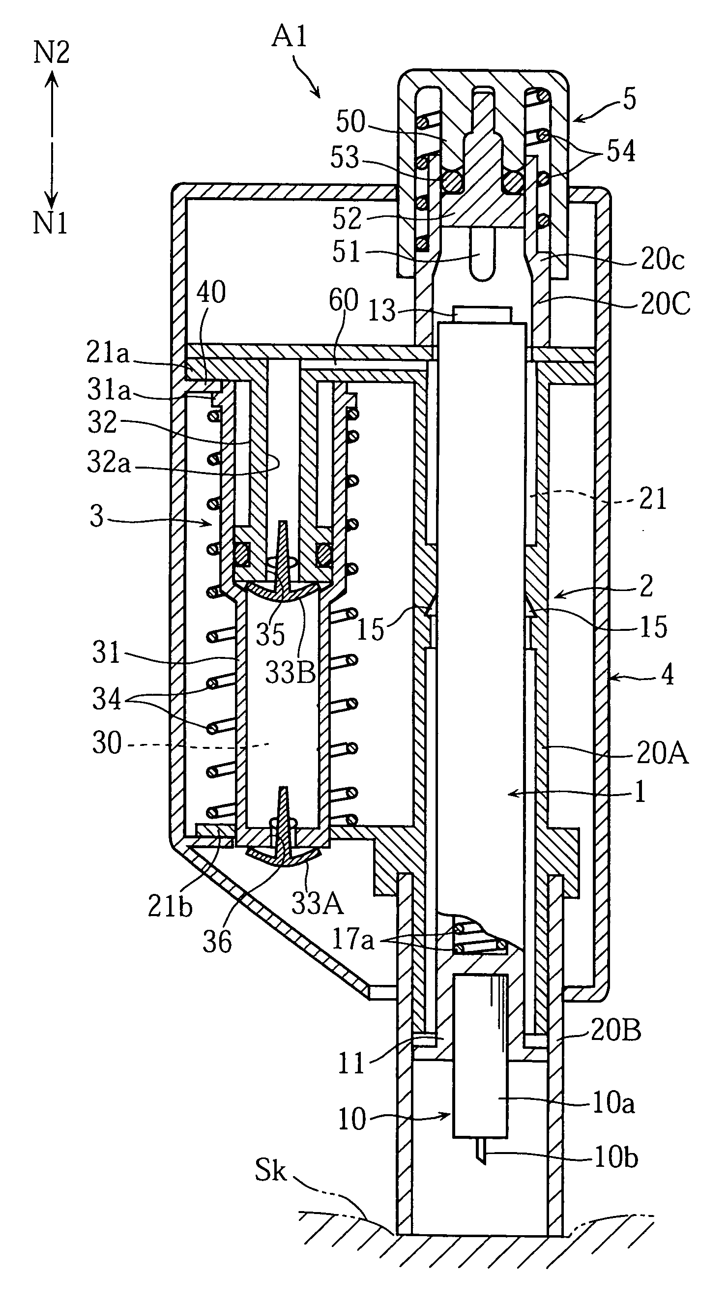
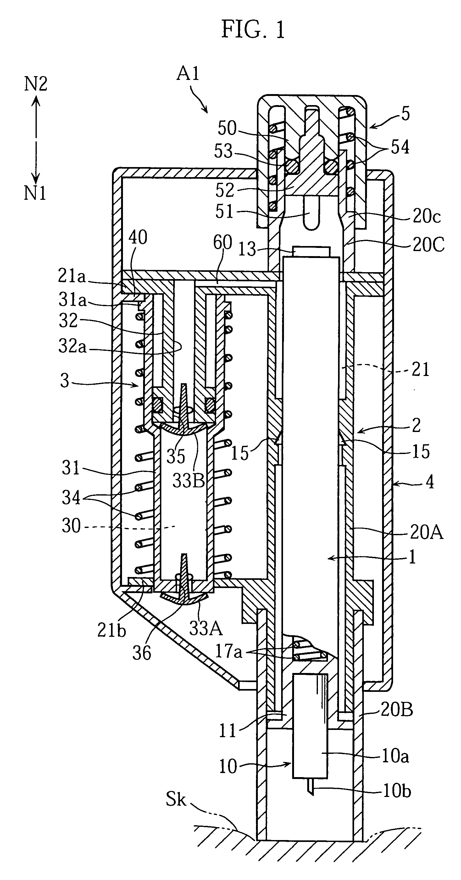
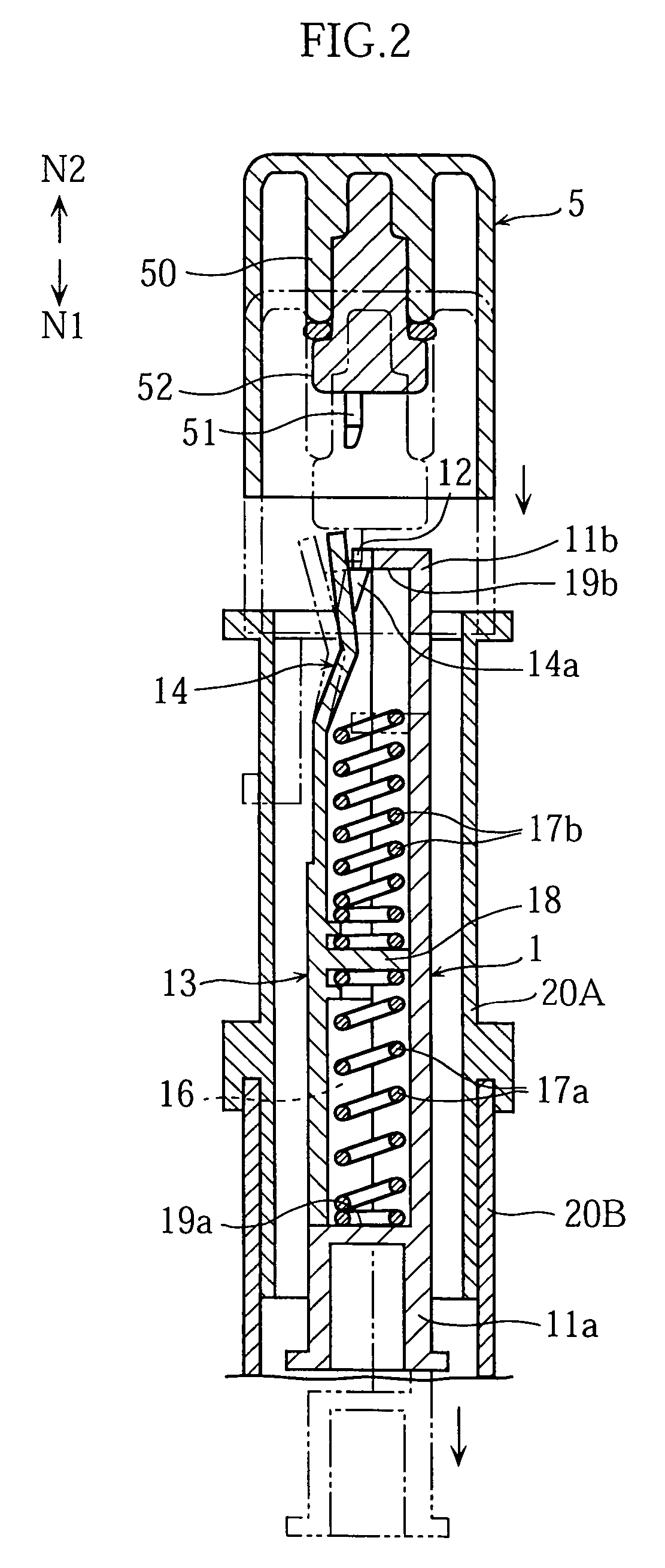
[0032]A fourth aspect of the present invention provides a method of making a lancing device comprising: a housing; a moving body movable relatively to the housing for forward movement of a needle; a driving mechanism for forward movement of the moving body; a hollow pressing portion at a front end of the housing for contact with a part where a puncture is to be made; a pressure chamber having a volumetric capacity varied by the reciprocation of the moving portion; and a pump mechanism capable of causing a vacuum to act inside the pressing portion. The pump mechanism is capable of adjusting the vacuum. A maximum vacuum to be generated inside the pressing portion is adjusted by selecting at least one of: a volumetric capacity of the pressure chamber when there is no outer force acting on the moving portion; and a maximum volumetric capacity increase possible in the pressure chamber when there is an outer force acting on the moving portion.

Problems solved by technology

However, the conventional lancing device has following drawbacks.
Therefore, from time to time depending on the vacuum in the housing 90, it is not possible to obtain a sufficient amount of bleeding, or the lancing causes too much bleeding.
Another problem is that conventionally, the vacuum can be created in the housing 90 only after the lancet L has been shot to the skin.
On the other hand, when lancing is to be made on a thin and easily relaxing part of the skin for example, it is sometimes more preferable that the a vacuum should be created first to suck on the skin, before shooting the lancet L. However, this is not available in the convention, and has been an issue of inconvenience some times.
Further, users of lancing devices are often clinical patients or the aged who do not have physical or bodily advantages.

Method used


Image

  • Lancing device, method of making lancing device, pump mechanism, and sucking device
  • Lancing device, method of making lancing device, pump mechanism, and sucking device
  • Lancing device, method of making lancing device, pump mechanism, and sucking device

Examples


second embodiment

[0099]Next, a lancing device A2 according to the present invention will be described with reference to FIG. 12. In FIG. 12, members and elements identical with or similar to those in the lancing device A1 described already are given the same alphanumeric codes and their description will not be repeated here.

[0100]As shown in FIG. 12, the lancing device A2 has a different lancing mechanism from the one used in the lancing device A1. This lancing mechanism includes a lancet holder 1A, an operative cap 5A, a forward propelling spring 17a and a rearward propelling spring 17b.

[0101]In the lancing device A2, the lancet holder 1A includes a plurality of latching pawls 12A. These latching pawls 12A engage with steps 14A in the housing 2A. The engagement with the steps 14A by the latching pawls 12A can be achieved by pushing the lancet holder 1A from the front end side toward the base end side of the housing 2A.

[0102]The operative cap 5A is slidably fitted into an operative casing 4. To the...

third embodiment

[0107]Next, a lancing device A3 according to the present invention will be described with reference to FIG.13. In this diagram, members and elements identical with or similar to those in the lancing device A1 and A2 described already are given the same alphanumeric codes and their description will not be repeated here.

[0108]As shown in FIG. 13, the lancing device A3 has a pump mechanism 3A perpendicular to the direction N1 or the direction in which the lancet 10 moves. Accordingly, an operative casing 4A includes a first portion 41 incorporating a lancet holder 1A and others, and a second portion 42 extending perpendicularly (in a direction N4) from the first portion 41 and incorporating the pump mechanism 3A.

[0109]The pump mechanism 3A uses basically the same arrangement as in the lancing device A1. Specifically, the pump mechanism 3A includes a plunger 32A having an air intake port 35, a cylinder 31A having an air discharge port 36 and forming a pressure chamber 30 together with t...

fourth embodiment

[0112]Next, a lancing device A4 according to the present invention will be described with reference to FIG. 14A and FIG. 14B. In these figures, members and elements identical with or similar to those in the lancing devices A1 through A3 described already are given the same alphanumeric codes and their description will not be repeated here.

[0113]In the lancing device A4, as shown in FIG. 14A and FIG. 14B, a vacuum can be created by reciprocation of an operative lever 59A in directions indicated by arrows N5, N6. Again in this embodiment, the lancing device A4 includes a pump mechanism 3B which is similar to those used in the lancing devices A1 through A4. However, the actual arrangement used for the pump mechanism is basically the same as in the lancing device A1. Specifically, the pump mechanism 3B includes a cylinder 31B, a plunger 32B, a return spring 34, and check valves (not illustrated).

[0114]An operative casing 4B includes two supports 43A, 43B. The support 43A pivotably suppo...


PUM


Abstract

A lancing device according to the present invention includes: a housing; a moving body movable relatively to the housing for forward movement of a needle; a driving mechanism for forward movement of the moving body; a hollow pressing portion at a front end of the housing for contact with a part where a puncture is to be made; and a pump mechanism capable of causing a vacuum to act inside the pressing portion. The pump mechanism is capable of adjusting the vacuum. The pump mechanism includes for example: a moving portion capable of reciprocating in a first direction and a second direction away from the first direction. Preferably, the adjustment of the vacuum is made by changing the number of reciprocations of the moving part in the first and the second directions.

Description

TECHNICAL FIELD[0001]The present invention relates to a lancing device used for sticking a needle into the skin when taking test samples of blood, other body fluid or tissues, and to a method of manufacturing the lancing device.[0002]The present invention further relates to a pump mechanism suitable for creating a vacuum on the skin, and to a sucking device for sucking on the skin.BACKGROUND ART[0003]Conventionally, a lancing device of this kind is disclosed in the Japanese Patent Laid-Open No. 11-9577 for example. The lancing device disclosed in this gazette includes, as shown in FIG. 31 of this application, a generally tubular housing 90 and a lancet holder 92 holding a lancet L. The housing 90 has an end fitted with a tubular plunger 93 having a check valve 91. Though details will not be described here, according to this lancing device, when the plunger 93 is pushed in a direction shown by an arrow Na, the lancet holder 92 latched at a predetermined place in the housing 90 is for...

Claims


Application Information

Patent Timeline
IPC IPC(8): A61B17/14A61B5/15
CPCA61B5/1411A61B5/15186A61B5/150022A61B5/150068A61B5/150099A61B5/150412A61B5/150503A61B5/15113A61B5/15117A61B5/1519A61B5/15194A61B5/1405
Inventor SATO, YOSHIHARUHIRAO, ETSUOFUKUZAWA, MASAHIROUCHIGAKI, TAKATOSHI
Owner ARKRAY INC
Learn More