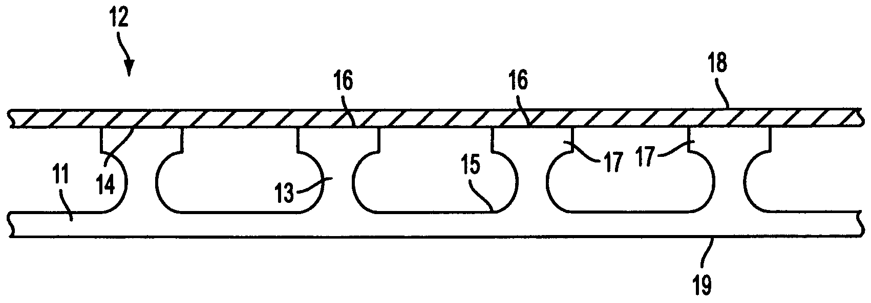
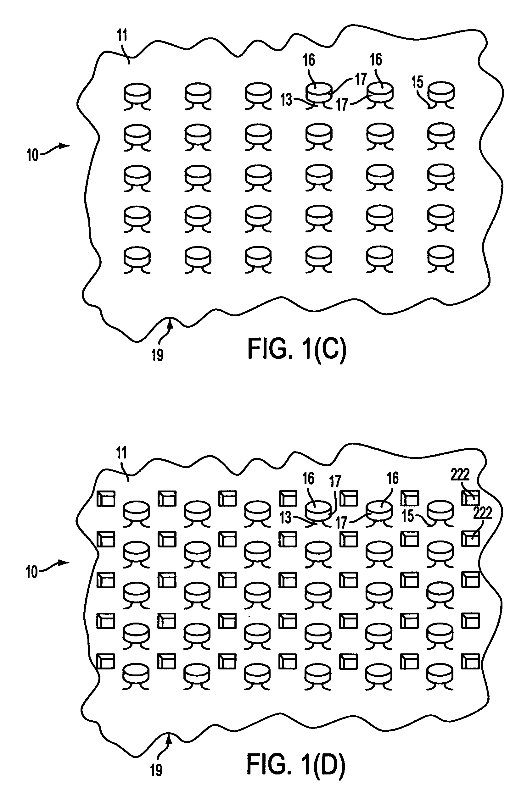
Water is a principal cause of distress and damage to paved structures such as roadways, airport runways and parking lots.
Fluids such as water that become trapped or retained within structural fill cause damage to roadways and, over time, subsequently greatly reduce the useful life of a pavement
system.
The cause of many premature pavement failures has been traced to inadequate
subsurface drainage.
In northern tier states, the destructive nature of water trapped in the structural base is exacerbated by freeze-thaw cycles, and particularly during spring thaw as ice lenses melt to create water-filled voids and very soft, water-
saturated soils which lose a substantial amount of their
compressive strength.
In turn, these phenomena result in extensive damage to the
highway system.
When there is a high fluid content within soil or other
layers supporting pavement that carries vehicular traffic, reduced
bearing capacity can occur, resulting in deformation of the contour of the
road surface, wheel rutting, and premature collapse or failure of the roadway.
For example, the presence of water in pavement causes a reduction of the
resilient modulus, which reduces the ability of a pavement surface to support traffic loads.
Moreover, added
moisture in unbound
aggregate base and sub-base
layers was estimated to result in a loss of stiffness on the order of 50% or more.
In addition, with inadequate drainage, saturated fine-grain road-
bed soil may experience modulus reductions of over 50%.
Furthermore, the presence of fluids often causes the buildup of hydraulic pore pressure that, in turn, reduces the
effective stress capacity of the soil materials that were placed to support the pavement
system.
Premature failure of pavement systems results in unacceptably high life-cycle costs for highways and other large paved structures.
After years of expense and effort, however,
waterproofing paved surfaces sufficiently to extend their useful life has proven to be quite challenging and somewhat unsuccessful.
Moreover, other studies that reviewed pavements constructed to include
base course layers constructed of non-uniform
gradation, and consequently non-uniform and insufficient drainage capacity, concluded that service life was actually decreased by 50% when the pavement was saturated for periods as small as 10% of the year, that is, for approximately one month per year.
Indeed, KYDOT concluded that the costs of failing to properly drain a road could be up to $500,000 per
mile when the costs of safety and repair delays are considered.
As can be easily seen, premature pavement failure due to inadequate drainage is an extremely serious and costly problem affecting the
transportation infrastructure of North America and other areas.
Nonetheless, there are many disadvantages in OGBC drainage systems that appear to be caused by the lack of mechanical and dimensional stability provided by using
uniform size gradations of stone.
Although such gradations create interconnecting void spaces or holes with the aggregate for the purpose of receiving and transmitting fluid, OGBC by its very nature is susceptible to unacceptable amounts of
lateral movement when exposed to shear stresses caused by typical traffic loading.
Other disadvantages pertain to the additional elements that are required in an OGBC installation.
This extra filter layer further increases the costs of the roadway construction.
Although an OGBC's interconnected void spaces may afford an acceptable level of drainage for some applications, the use of an OGBC conflicts with many established road pavement design practices.
Furthermore, unacceptably high construction costs are sometimes incurred when using an OGBC because of the need for precision and extensive on-
site quality control in order to increase the chances that a high-flow OGBC
system will last for the life of the overlying paved surface.
Another particular problem with the use OGBC's for drainage relates to their long-term performance.
It is not uncommon to find distress in some OGBC systems after only a few years of apparently satisfactory service.
Initial indications are that the drainage from the system has slowed and that the pavement and one or more base layers are moving with respect to one another, resulting in loss of sufficient support to overlying pavement layers.
Some researchers and practitioners have suggested that the failure of an open-graded
base course as a drainage layer is far more detrimental to the stability of a paved surface then the presence of a fluid-saturated dense-graded
base course.
The
hydraulic conductivity of OGBC's over time is susceptible to the deleterious clogging effects of the upward migration of
subgrade soil particles into the layer, as well as from the infiltration of fine particles from fractures in the pavement surface.
Yet another problem with the OGBC is that quality aggregate is not always available or, if available, at uneconomically or prohibitively high costs.
Until recently, the only geosynthetic materials available for pavement drainage were exclusively limited to drains at the edge or shoulder of a roadway.
Conventional edge drain
geosynthetics, however, cannot withstand the repeated dynamic loads that are present directly beneath pavement surfaces.


