
Dynamic storage device pooling in a computer system

Active Publication Date: 2006-10-31
COMMVAULT SYST INC
View PDF89 Cites 848 Cited by
  • Summary
  • Abstract
  • Description
  • Claims
  • Application Information

AI Technical Summary

Benefits of technology

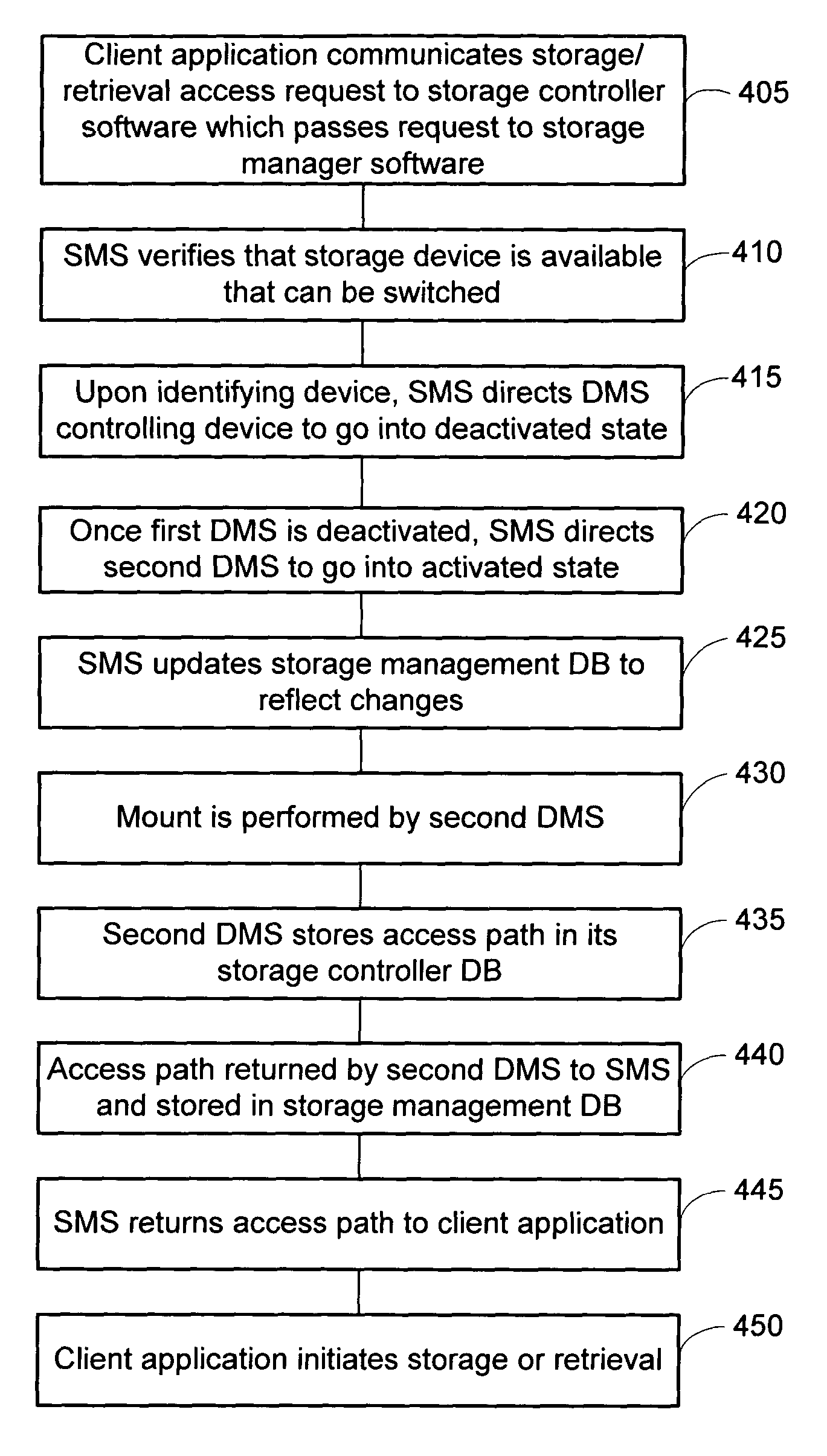
[0027]In some embodiments, error recovery protocols exist such that if a particular storage controller computer or storage controller computer's DMS is unavailable, then the storage manager computer assigns control of a particular storage device to a different storage controller computer. Such reassignment by the storage manager computer creates a more fault-tolerant storage architecture and ensures that the malfunctioning or lack of availability of a particular storage controller computer or storage controller computer's DMS does not affect the other storage controller computers and their DMSs.

Problems solved by technology

One problem associated with these storage architectures relates to overloading network traffic during certain operations associated with use of storage devices on the network.
Network cables have a limited amount of bandwidth that must be shared among all the computers on the network.
During common operations such as system backups, transaction processing, file copies, and other similar operations, network traffic often becomes overloaded as hundreds of megabytes (MB) and gigabytes (GB) of information are sent over the network to the associated storage devices.
The capacity of the network computers to stream data over the network to the associated storage devices in this manner is greater than the bandwidth capacity of the cabling itself, thus substantially slowing ordinary network and storage activity and communications.
Thus, when the bandwidth-intensive operations are required, they take place over the SAN and the LAN remains unaffected.
Even with a SAN, however, the static relationship between individual storage controller computers and individual storage devices or drive pools causes bandwidth difficulties during data storage or retrieval operations.
Thus, one computer on a network cannot control the drive pool and media group being controlled by another, and requests to store and retrieve data from such a drive pool and media group would have to first pass through the controlling computer.
This relationship between storage controller computer and storage device continues to lead to bandwidth difficulties.
In addition, the current architectures result in inefficient use of resources and the need for extra storage devices or pools beyond the actual storage needs of the network.

Method used


Image

  • Dynamic storage device pooling in a computer system
  • Dynamic storage device pooling in a computer system
  • Dynamic storage device pooling in a computer system

Examples


Embodiment Construction

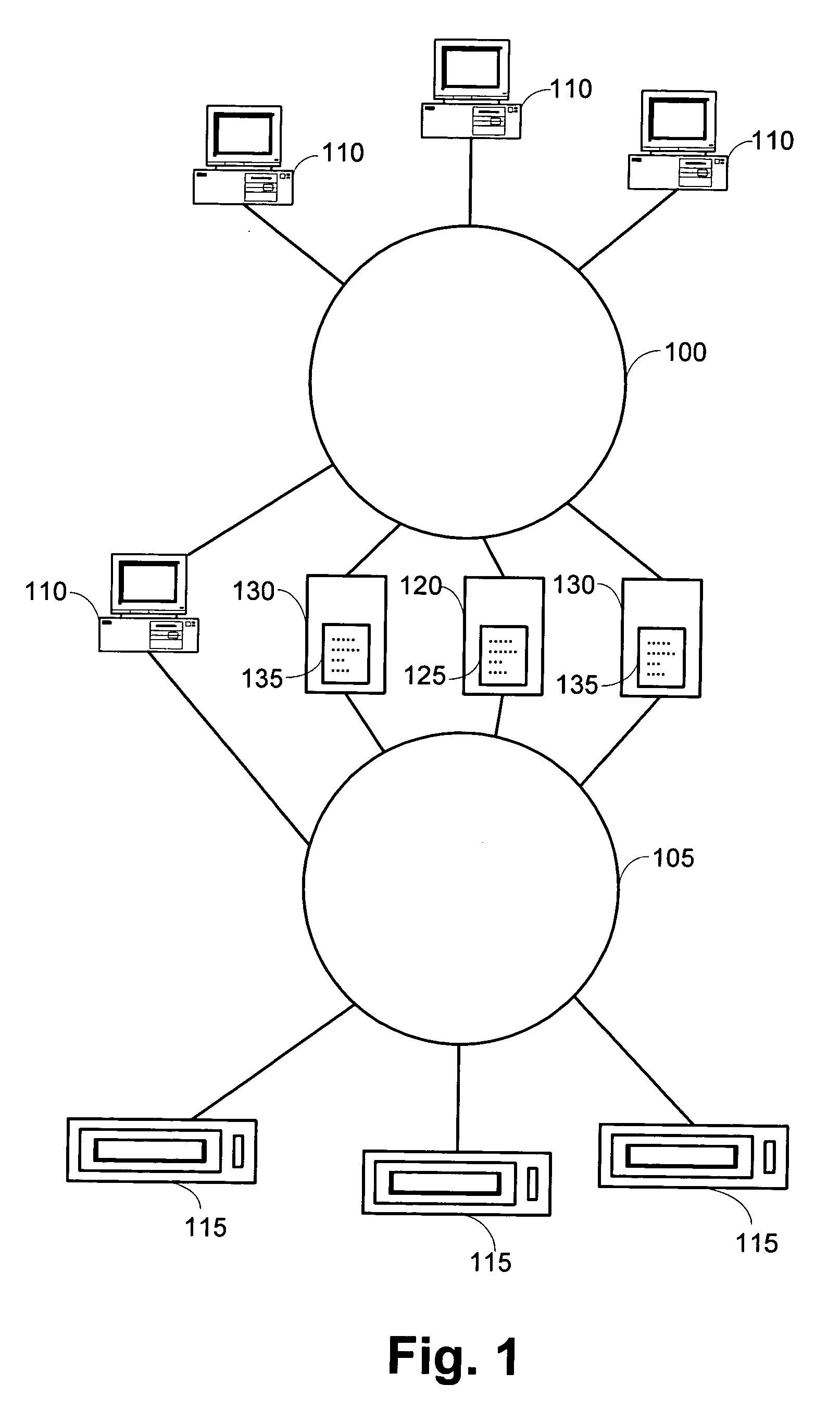
[0035]Preferred embodiments of the invention are now described with reference to the drawings. An embodiment of the system of the present invention is shown in FIG. 1. As shown, the system includes a Local Area Network 100 and a Storage Area Network 105. The LAN will typically use 10 / 100 mbps Ethernet or other similar cable and communicate using TCP / IP. The SAN will typically use higher-bandwidth cabling such as a fiber channel and will use a different network communication protocol such as SCSI-3, CommVault Systems' DataPipe™, or other similar protocol optimized for network storage and retrieval of electronic data.

[0036]Network clients 110 are connected to the LAN 100 and in some embodiments also connected to the SAN 105. These network clients 110 contain the electronic data that the will travel over the network and be stored on or retrieved from the storage devices 115 attached to the SAN 105. The storage devices 115 may be tape drives, optical libraries, RAID, CD-ROM jukeboxes, o...


PUM


Abstract

A method for dynamically allocating control of a storage device, the method comprising receiving an access request from a first computer requesting access to a storage device; directing, based upon the access request, a first storage controller computer to assume an inactive state with respect to control of the storage device; and directing, based upon the access request, a second storage controller computer to assume an active state with respect to control of the storage device.

Description

CROSS-REFERENCE TO RELATED APPLICATIONS[0001]This Application for Patent claims the benefit of priority from, and hereby incorporates by reference the entire disclosure of U.S. Provisional Application Ser. No. 60 / 409,183, titled DYNAMIC STORAGE DEVICE POOLING IN A COMPUTER SYSTEM, filed Sep. 9, 2002.RELATED APPLICATIONS[0002]This application is also related to the following pending applications, each of which is hereby incorporated herein by reference in its entirety:[0003]Application Ser. No. 09 / 610,738, titled MODULAR BACKUP AND RETRIEVAL SYSTEM USED IN CONJUNCTION WITH A STORAGE AREA NETWORK, filed Jul. 6, 2000;[0004]Application Ser. No. 09 / 609,977, titled MODULAR BACKUP AND RETRIEVAL SYSTEM WITH AN INTEGRATED STORAGE AREA FILING SYSTEM, filed Aug. 5, 2000;[0005]Application Ser. No. 09 / 354,058, titled HIERARCHICAL BACKUP AND RETRIEVAL SYSTEM, filed Jul. 15, 1999; and[0006]Application Ser. No. 09 / 038,440, titled HIGH-SPEED DATA TRANSFER MECHANISM, filed Mar. 11, 1998.COPYRIGHT NOT...

Claims


Application Information

Patent Timeline
IPC IPC(8): G06F12/00G06F3/06G06F12/16G06F13/00G06F13/14G06F17/30H04L29/08
CPCG06F3/0613G06F3/0635G06F3/067H04L67/1097G06F16/10G06F13/14
Inventor DEVASSY, VARGHESEKOTTOMTHARAYIL, RAJIVKUMAR, MANOJ
Owner COMMVAULT SYST INC
Learn More