
Self calibrating receive path correction system in a receiver

Active Publication Date: 2006-10-31
GOOGLE TECH HLDG LLC
View PDF14 Cites 84 Cited by
  • Summary
  • Abstract
  • Description
  • Claims
  • Application Information

AI Technical Summary

Problems solved by technology

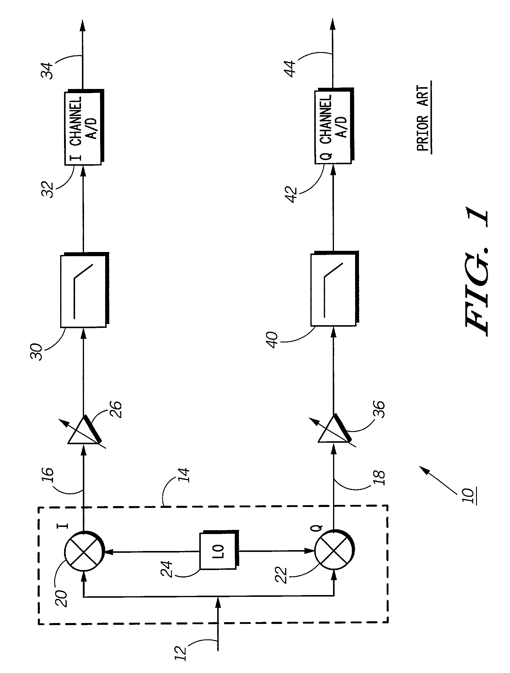
Gain and phase imbalances between the I and Q quadrature channels of a receive signal path of a communication device occur because of inherent circuit level mismatches between analog circuits in these quadrature signal paths.
This can significantly degrade the detectability of the received signal under both static as well as multipath fading channel conditions for both Zero Intermediate Frequency (IF) as well as Very Low Intermediate Frequency (VLIF) receivers.
Traditionally, it has been difficult to achieve such I / Q performance without performing open loop factory calibration steps.
This is unfortunately an expensive approach as it adds to production cost and time.
Even if factory calibration is performed, it is difficult to preserve the factory correction performance over temperature, supply voltage, and channel frequency variations over the life of the wireless product.
The total gain imbalance due to these circuits can exceed 4 dB over process, temperature, and supply voltage variations.
For amplitude-modulated systems, the gain imbalance requirements are even more stringent.
The total phase imbalance due to these circuits can exceed 10 degrees over process, temperature, supply voltage, and channel frequency variations.

Method used


Image

  • Self calibrating receive path correction system in a receiver
  • Self calibrating receive path correction system in a receiver
  • Self calibrating receive path correction system in a receiver

Examples


Embodiment Construction

)

[0018]As required, detailed embodiments of the present invention are disclosed herein; however, it is to be understood that the disclosed embodiments are merely exemplary of the invention, which can be embodied in various forms. Therefore, specific structural and functional details disclosed herein are not to be interpreted as limiting, but merely as a basis for the claims and as a representative basis for teaching one skilled in the art to variously employ the present invention in virtually any appropriately detailed structure. Further, the terms and phrases used herein are not intended to be limiting; but rather, to provide an understandable description of the invention.

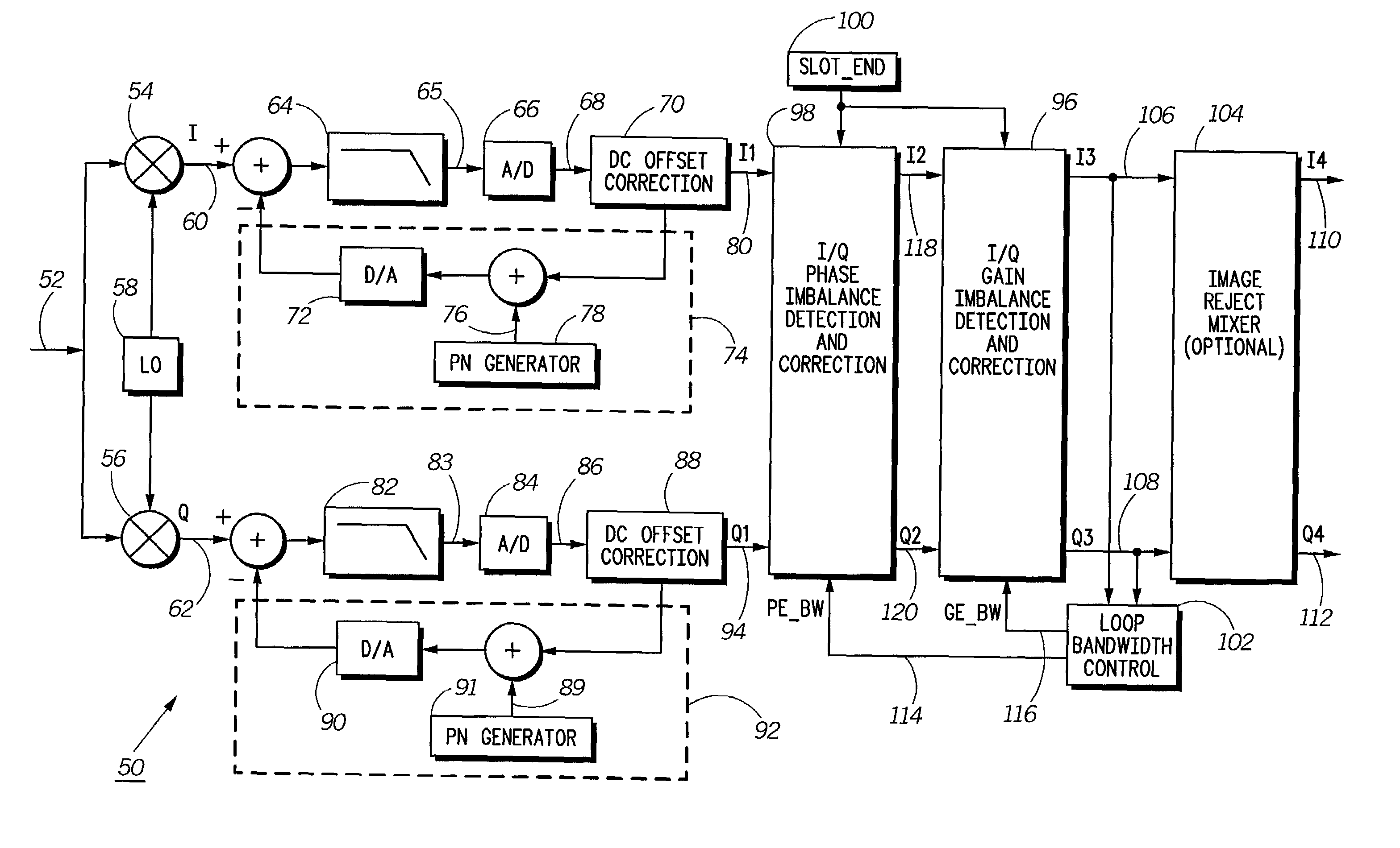
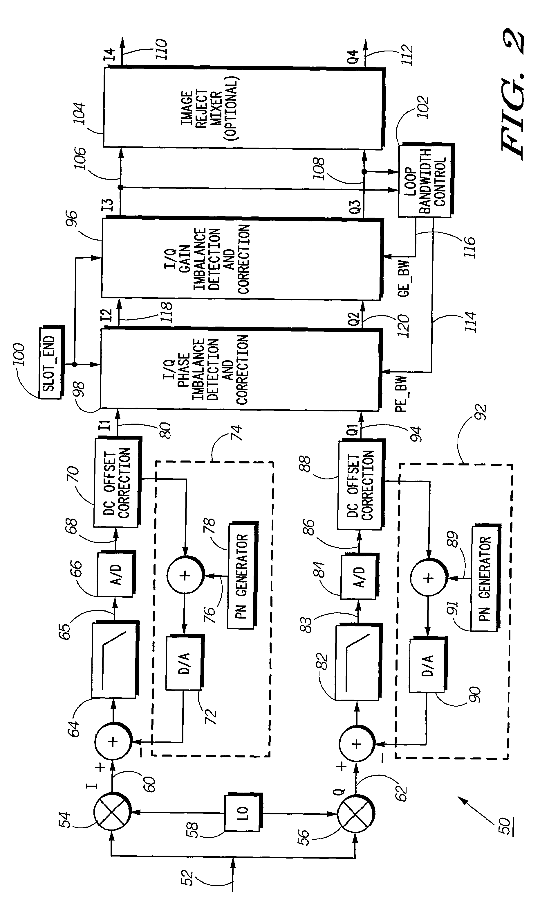
[0019]FIG. 2 illustrates an electronic block diagram of a receiver 50 for correction of I / Q quadrature gain and phase imbalances in the receive signal path of a communication device in accordance with the preferred embodiment of the present invention. The receiver 50 preferably comprises a Zero IF (ZIF) or Very lo...


PUM


Abstract

A receiver (50) includes a self-calibrating receive path correction system for correction of I / Q gain and phase imbalances in a radio frequency signal. The system includes a signal-processing block (53), an I / Q phase imbalance detection and correction circuit (98), an I / Q gain imbalance detection and correction circuit (96), and an adaptive loop bandwidth control circuit (102). The I / Q phase imbalance detection and correction circuit (98) equalizes for the relative phase imbalance and the I / Q gain imbalance detection and correction circuit (96) equalizes for the relative gain imbalance between the I and Q channels created by the analog portion of a quadrature receiver. The adaptive loop bandwidth control circuit (102) dynamically adjusts at least one loop bandwidth for the I / Q gain imbalance detection and correction circuit (96) and the I / Q phase imbalance detection and correction circuit (98) on a slot boundary.

Description

BACKGROUND OF THE INVENTION [0001]1. Field of the Invention[0002]This invention relates in general to communication devices and in particular to communication devices incorporating a receive signal path correction system with self-calibration capabilities.[0003]2. Description of the Related Art[0004]Gain and phase imbalances between the I and Q quadrature channels of a receive signal path of a communication device occur because of inherent circuit level mismatches between analog circuits in these quadrature signal paths. This can significantly degrade the detectability of the received signal under both static as well as multipath fading channel conditions for both Zero Intermediate Frequency (IF) as well as Very Low Intermediate Frequency (VLIF) receivers. In addition, in the case of VLIF receivers, the performance of these receivers is highly dependent on the suppression of the image signal. Suppression of the image signal in such receivers can be significantly improved by eliminat...

Claims


Application Information

Patent Timeline
IPC IPC(8): H03K9/00H03D3/00H04B1/707
CPCH03D3/008H03D3/009H04B1/707
Inventor RAHMAN, MAHIBUR
Owner GOOGLE TECH HLDG LLC
Learn More