
System and method for fault contactor detection

a technology of contactor and system, applied in the field of motor controller, can solve problems such as motor damage, contactor not opening,

Active Publication Date: 2006-10-31
SIEMENS ENERGY & AUTOMATION INC
View PDF7 Cites 65 Cited by
  • Summary
  • Abstract
  • Description
  • Claims
  • Application Information

AI Technical Summary

Benefits of technology

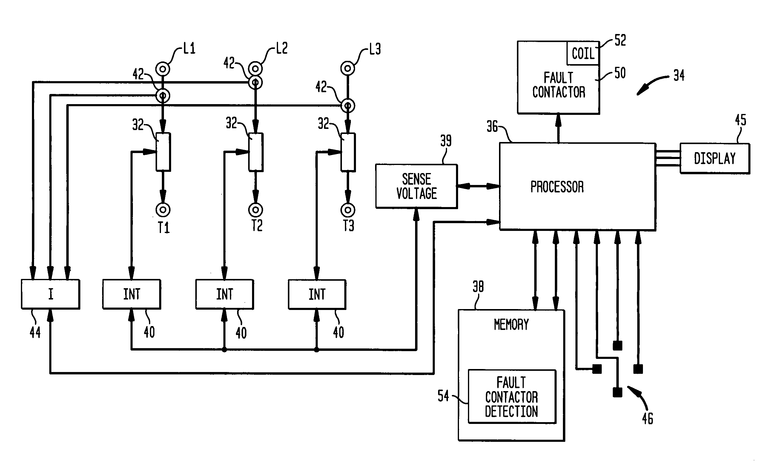
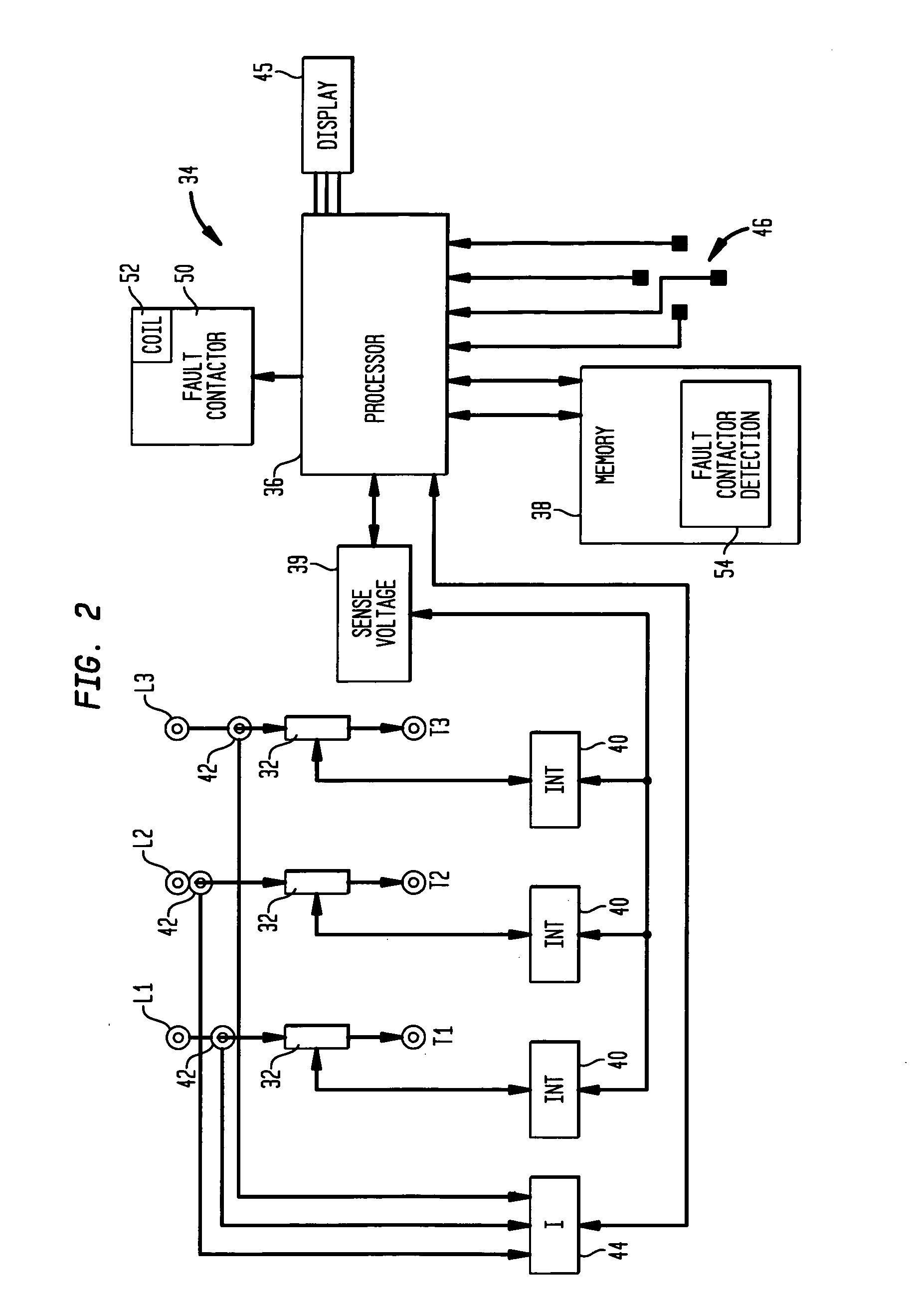
"The invention provides a system and method for detecting fault contactors in a motor controller system. The system includes power switches, a fault contactor, and voltage sensors to measure the voltage at the AC line and the motor winding terminals. The control circuit selectively de-energizes the fault contactor when the motor is not under load and detects an error condition if there is a significant difference in the voltage levels or a different phase relationship between the AC line voltage and the motor winding terminal voltage. This allows for quicker detection and replacement of fault contactors, improving the reliability and efficiency of the motor controller system."

Problems solved by technology

However, there may be instances where the fault contactor control coil is not wired properly, which could result in a condition where the fault contactor does not open in a fault condition.
This could result in a damaged motor.

Method used


Image

  • System and method for fault contactor detection
  • System and method for fault contactor detection
  • System and method for fault contactor detection

Examples


Embodiment Construction

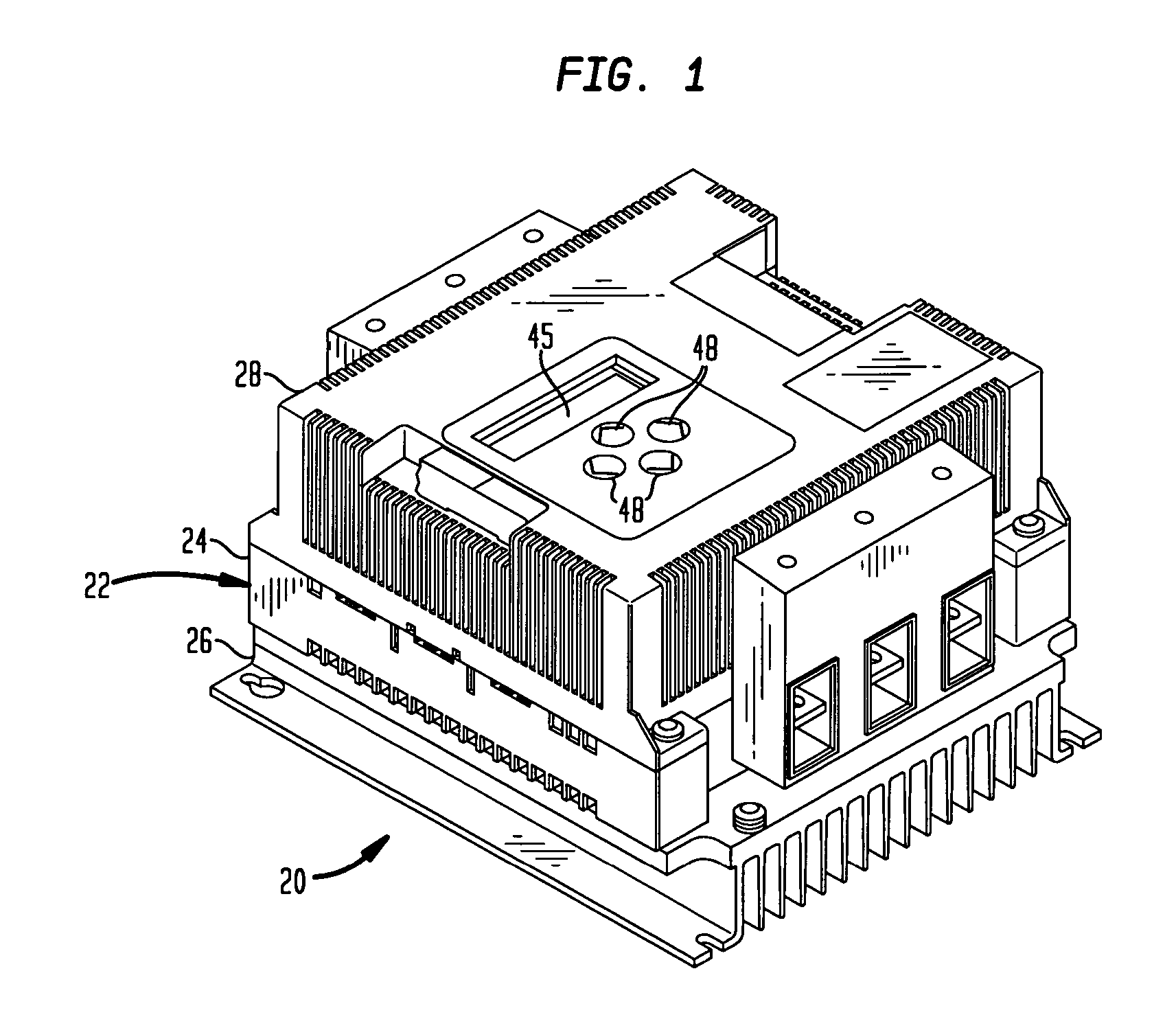
[0022]Referring initially to FIG. 1, a solid state motor starter / controller 20, referred to hereinafter as simply a starter or a controller, is illustrated. One application for the controller 20 is as an elevator starter. The motor controller 20 may be used to drive a pump for an hydraulic elevator. Each time movement of an elevator car is commanded, the motor controller 20 must start the elevator motor until it reaches operating speed and then operate in a run mode. Such a motor controller 20 may only be used for the up direction as gravity may be used for the down direction.

[0023]The motor controller 20 comprises a housing 22 including a housing base 24, a heat sink 26 and a cover 28. The motor controller 20 includes a plurality of solid state power switches 32 in the form of thyristors, such as back to back connected silicon controlled rectifier (SCR) pairs, see FIG. 2. For simplicity herein, the SCR pairs 32 are referred to as simply SCRs. Triacs could also be used. The SCRs 32 ...


PUM


Abstract

A motor starter system comprises solid state switches for connection to an AC line for controlling application of AC power to the motor. A fault contactor has contacts. A motor wiring circuit operatively connects the solid state switches and fault contactor contacts with motor winding terminals. A voltage sensor senses AC line voltage and motor terminal voltage. A control circuit controls operation of the solid state switches and the fault contactor, including de-energizing the fault contactor in an off mode where AC line power is not supplied to the motor winding terminals. The control circuit detects AC line voltage and motor terminal voltage in the off mode and detect an error condition responsive to sensed AC line voltage being substantially different from motor terminal voltage in the off mode.

Description

CROSS REFERENCE TO RELATED PATENT APPLICATIONS[0001]The present U.S. Patent Application having at least one common inventor as[0002]U.S. patent application Ser. No. 10 / 786,320 entitled “System and Method for Configuring a Soft Starter”, and[0003]U.S. patent application Ser. No. 10 / 786,319 entitled “System and Method for Providing Electrical System Monitoring and Diagnosis”, and being filed with the U.S. Patent and Trademark Office concurrently on Feb. 25, 2004, the entirety of each is incorporated herein by reference.FIELD OF THE INVENTION[0004]This invention relates to a motor controller and more particularly, a system and method for fault contactor detection.BACKGROUND OF THE INVENTION[0005]Solid state starters / controllers have found widespread use for controlling application of power to an AC induction motor. The conventional starter / controller, referred to hereinafter as simply a starter or a controller, uses solid state switches for controlling application of AC line voltage to...

Claims


Application Information

Patent Timeline
Patent Type & Authority Patents(United States)
IPC IPC(8): H02H5/04H02H7/08H02H11/00
CPCH02H7/0816H02H11/004H02H7/0833
Inventor WAKEFIELD, SCOTTZUZULY, DANIELMAYHEW, SCOTT
Owner SIEMENS ENERGY & AUTOMATION INC
Learn More