Eureka AIR delivers breakthrough ideas for toughest innovation challenges, trusted by R&D personnel around the world.

Image recording apparatus, image recording method, method for controlling the image recording apparatus, storage medium storing a program capable of being read by a computer, and image processing method

a technology for recording apparatus and image, which is applied in the field of image recording apparatus, image recording method, and image recording apparatus, can solve the problems of degrading image quality, inability to sufficiently prevent the degradation of image quality, and inability to observe the effect of reducing the size of each dot pattern, reducing the capacity of dot-pattern table and the cost of the apparatus

Inactive Publication Date: 2006-10-31
CANON KK
View PDF31 Cites 40 Cited by
  • Summary
  • Abstract
  • Description
  • Claims
  • Application Information

AI Technical Summary

Benefits of technology

[0012](1) The present invention has been made in consideration of the above-described problems in approach (i). It is an object of the present invention to provide an image recording method which can record a high-quality image while reducing unevenness in the density, unevenness due to stripes, and the like, in the recorded image when recording the image by performing pseudo-halftone processing, an image recording apparatus for recording such an image, a method for controlling the image recording apparatus, a storage medium capable of being read by a computer, and an image processing method.
[0013](2) The present invention has also been made in consideration of the above-described problems in approach (ii). It is another object of the present invention to provide an image recording method and an image recording apparatus which can reduce the capacity of data of a dot-pattern table while preventing the occurrence of unevenness in the density and unevenness due to stripes in the recorded image, a method for controlling the image recording apparatus, and a storage medium capable of being read by a computer. It is still another object of the present invention to provide a low-cost image recording apparatus by reducing the capacity of data of a dot-pattern table.
[0014](3) The present invention has also been made in consideration of the above-described problems in approach (iii). It is yet another object of the present invention to provide an image recording apparatus, an image recording method, and an image processing method which can reduce the size of a dot-pattern table while maintaining the quality of recording.
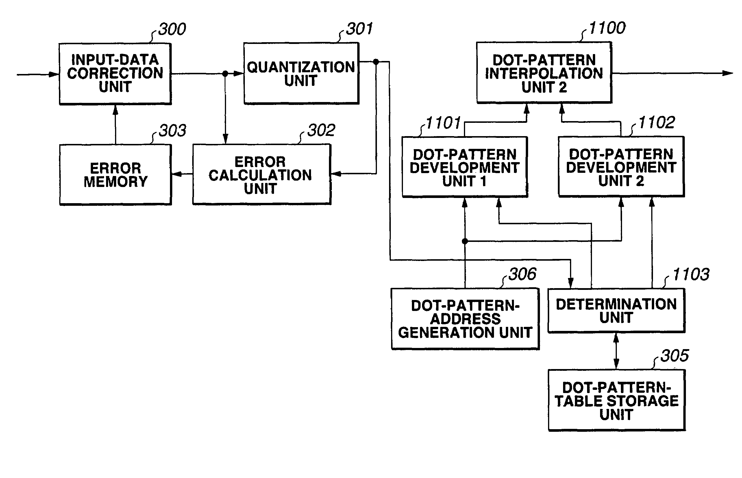
[0039]According to the present invention having the above-described configurations, when recording a pseudo-halftone image using dot patterns, a dot-pattern table storing a plurality of different dot patterns is provided for each of gradation values. One dot-pattern table is selected from among N dot-pattern tables based on gradation-value information indicated by each pixel. Then, one dot pattern is selected from the selected dot-pattern table based on position information indicated by the pixel, and recording is performed using the selected dot pattern. It is thereby possible to prevent the concentrated use of a specific nozzle, and to suppress the occurrence of unevenness in the density due to the characteristics of the specific nozzle.
[0068]More specifically, when performing color recording using recording materials having a plurality of colors, by utilizing the fact that there are colors in which stripes and unevenness in the recorded image are easily observed and colors in which stripes and unevenness in the recorded image are not easily observed, due to the human visual characteristics, the size of each dot pattern is increased for the colors of the former type, and the size of each dot pattern is reduced for the colors of the latter type. It is thereby possible to reduce the capacity of dot-pattern tables and the cost of the apparatus while maintaining the same recording quality as in the case of using large-size dot patterns for all colors.

Problems solved by technology

The density pattern method has problems in that the resolution is degraded when the block size is increased, and the number of gradation levels is small when the block size is reduced, resulting in degradation in the degree of gradation because smooth gradation representation is difficult to obtain.
If recording is performed using a dot pattern having a fixed arrangement of dots for each gradation level as in the above-described case, the recorded image tends to be influenced by variations in the characteristics of each nozzle, and unevenness in the density and unevenness due to stripes occur in the image, thereby greatly degrading the quality of the image.
However, if the pattern of dots to be output is a fixed dot pattern as described above, it is impossible, in some cases, to sufficiently prevent degradation of the quality of the image even by the multi-path recording control.
In this approach, however, the number of necessary dot-pattern tables increases as the number of gradation levels increases, thereby increasing the amount of data of the dot-pattern tables.
An increase in the amount of data requires a large-capacity memory, thereby increasing the cost of the recording apparatus.
This approach, however, requires a large-capacity memory.
If the size of the dot-pattern table is simply reduced in order to solve this problem, stripes and unevenness are pronounced in the recorded image, thereby degrading the quality of the image.

Method used


Image

  • Image recording apparatus, image recording method, method for controlling the image recording apparatus, storage medium storing a program capable of being read by a computer, and image processing method
  • Image recording apparatus, image recording method, method for controlling the image recording apparatus, storage medium storing a program capable of being read by a computer, and image processing method
  • Image recording apparatus, image recording method, method for controlling the image recording apparatus, storage medium storing a program capable of being read by a computer, and image processing method

Examples


first embodiment

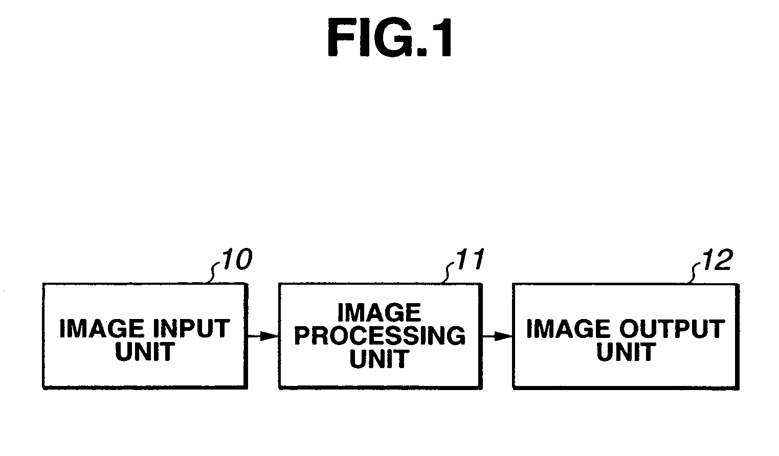
[0118]FIG. 1 is a schematic block diagram illustrating the configuration of an image processing system according to a first embodiment of the present invention.

[0119]In FIG. 1, an image input unit 10 inputs multi-valued image data from an image input apparatus, such as a scanner, a digital camera or the like, or multi-valued image data stored in each type of storage medium, such as a hard disk or the like. An image processing unit 11 performs image processing (to be described later) for the multi-valued image data input by the image input unit 10, to convert the multi-valued image data into a binary image data. An image output unit 12 receives the binary image data from the image processing unit 11, and performs actual image formation. Although not illustrated in FIG. 1, each of the units constituting the system includes a CPU (central processing unit) for controlling operations of the unit itself and linked operations with other units, a ROM (read-only memory) storing control progr...

second embodiment

[0183]In a second embodiment of the present invention, a multi-path recording method, in which recording on the same region of a recording medium is completed by performing scanning of the region by a recording head a plurality of times, is executed. In order to simplify the description, a case in which the same region is scanned twice will be described. Since the second embodiment is the same as the above-described first embodiment except that the multi-path recording method is executed, the above-described FIGS. 1–5, and FIGS. 8–12 can also be applied to the second embodiment. Hence, further description thereof will be omitted.

[0184]FIG. 13 is a schematic diagram illustrating how two-path recording is performed.

[0185]As shown in FIG. 13, every time the recording head performs one scanning operation, the recording medium is conveyed by ½ of the recording width of the recording head, so that recording is completed by two scanning operations on the same region of the recording medium...

third embodiment

[0191]A third embodiment of the present invention will now be described.

[0192]FIG. 23 is a block diagram illustrating the configuration of an image recording apparatus according to the third embodiment.

[0193]In FIG. 23, reference numeral 100 represents the entire image recording apparatus. An image input unit 101 inputs multi-valued image data from an image input apparatus, such as a scanner, a digital camera, or the like, or multi-valued image data stored in each type of storage medium, such as a hard disk, or the like. An image processing unit 102 performs image processing (to be described later) for the multi-valued image data-input by the image input unit 101, to convert the multi-valued image data into a binary image data. An image recording unit 103 receives the binary image data from the image processing unit 102, and performs actual image formation. Although not illustrated in FIG. 23, the operations and linked operations with other units of the units constituting the image ...


PUM


Abstract

When recording a gradation pixel by performing pseudo-halftone processing, the occurrence of unevenness in the density in the recorded image is suppressed. For that purpose, when recording a pseudo-halftone image using dot patterns, a dot-pattern table storing a plurality of different dot patterns is provided for each gradation value. One dot-pattern table is selected from N dot-pattern tables based on gradation-value information for each pixel. One dot pattern is selected from the selected dot-pattern table, based on position information indicated by the pixel, and recording is performed using the selected dot pattern. It is thereby possible to prevent the concentrated use of a particular nozzle of a recording head, and suppress the occurrence of unevenness in the density due to characteristics of the specific nozzle.

Description

BACKGROUND OF THE INVENTION[0001]1. Field of the Invention[0002]The present invention relates to an image recording method and an image recording apparatus for performing recording using a dot pattern where dot information is stored, a method for controlling the image recording apparatus, a storage medium storing a program capable of being read by a computer, and an image processing method.[0003]2. Description of the Related Art[0004]There has been a method called a density pattern method, as a method of pseudo-halftone processing for representing gradation by converting a multiple-valued image into a binary image. In this method, in order to represent continuous gradation in an image recording apparatus which can represent each pixel of an image only by binary values, a plurality of binary pixels are collected to form a block, and gradation is represented by a group of such pixel blocks. More specifically, dots are arranged within a dot-matrix cell comprising, for example, 2×2 or 4...

Claims


Application Information

Patent Timeline
Patent Type & Authority Patents(United States)
IPC IPC(8): H04N1/40G06K15/00H04N1/405H04N1/401
CPCH04N1/4015H04N1/4051
Inventor KONNO, YUJIISHIKAWA, HISASHITAJIKA, HIROSHIFUJITA, MIYUKIKAWATOKO, NORIHIROEDAMURA, TETSUYAMAEDA, TETSUHIRO
Owner CANON KK
Why Eureka
Eureka Blog
Learn More