
Methods of improving reliability of an electro-optical module

a technology of electrooptical modules and reliability, applied in the direction of optical elements, instruments, optical waveguide light guides, etc., can solve the problems of low cost to many thousands of dollars per, difficult alignment of optical fibers to active optical areas of light emitters or light detectors, and the deformation or malfunction of emitters, so as to achieve the effect of improving reliability

Inactive Publication Date: 2006-10-31
RPX CORP
View PDF15 Cites 37 Cited by
  • Summary
  • Abstract
  • Description
  • Claims
  • Application Information

AI Technical Summary

Benefits of technology

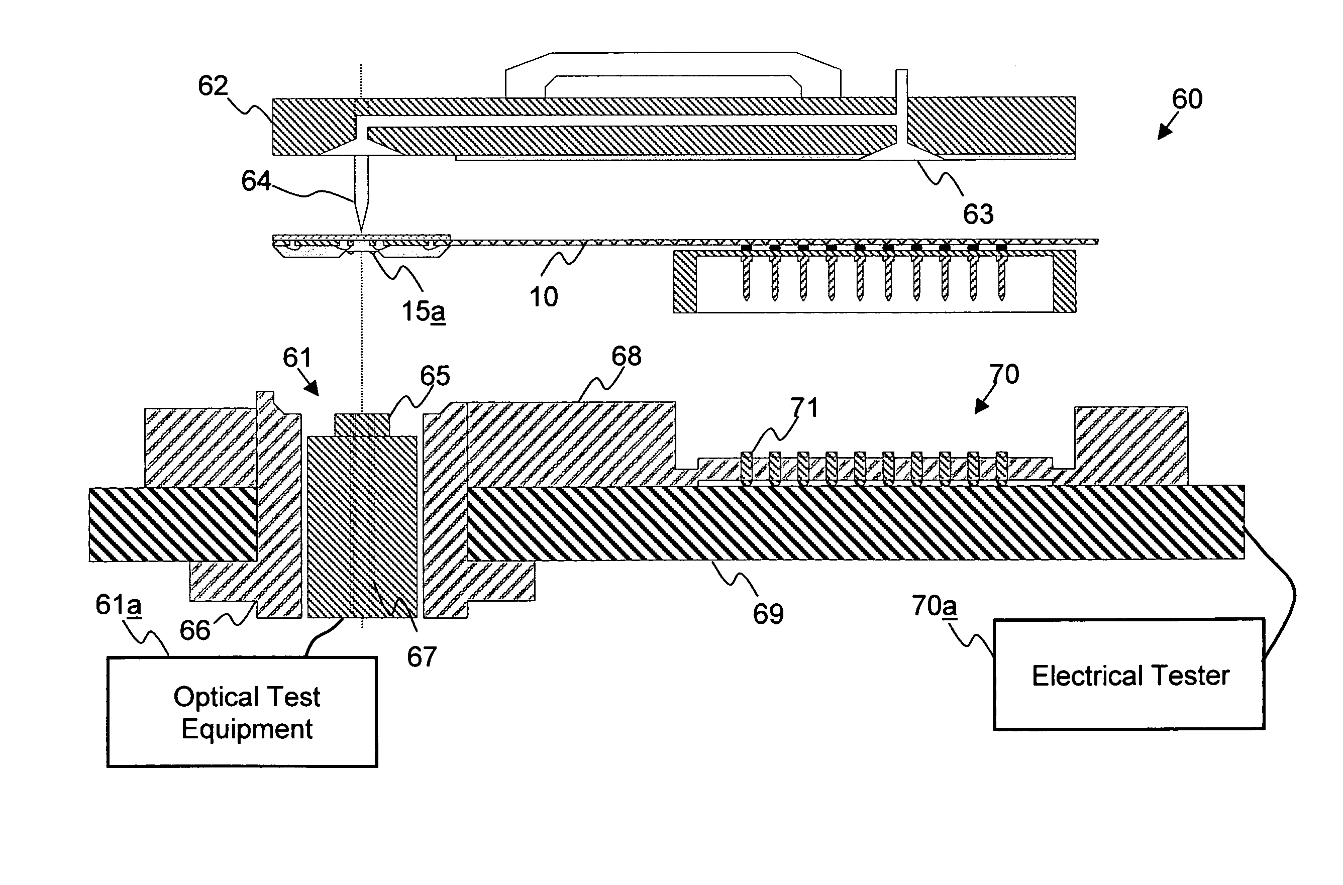
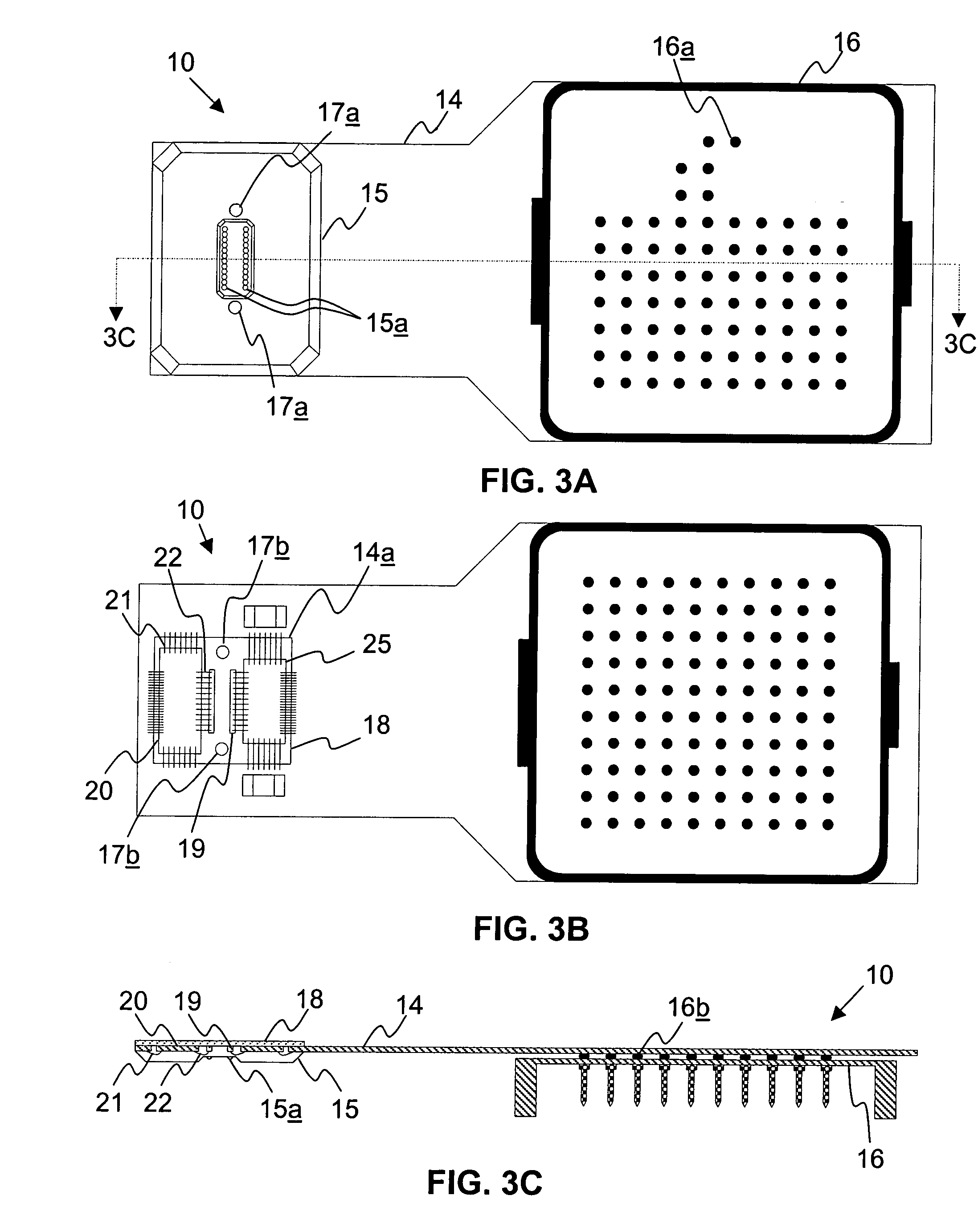
The patent text describes methods for improving the quality and reliability of electro-optical modules. The first method involves testing the electro-optical sub-assembly by positioning an electrical interface and an optical interface in communication with a test device. The test device can evaluate the performance of the sub-assembly while the tests are performed simultaneously. The second method involves burning in the sub-assembly by mounting it on a burn-in board and providing power and signals through mating electrical sockets. The sub-assembly can include a flexible printed circuit board and an electro-optical semiconductor device. The third method involves forming an electro-optical module by testing the sub-assembly and positioning it in an MTP receptacle with a heatsink. The sub-assembly is aligned in the MTP receptacle and the heatsink is secured. These methods improve the quality and reliability of electro-optical modules.

Problems solved by technology

These modules have many applications, particularly within data-communications technology where electrical signals are carried by fiber optics, and can range in cost from under a hundred dollars to many thousands of dollars per module, depending on their application and functionality.
There are several challenges, however, in manufacturing optical modules.
Among these challenges, it is difficult to align an optical fiber to an active optical area of a light emitter or a light detector.
In addition, emitters may degrade or malfunction at relatively low temperatures, and removing heat from the emitters can be difficult.
It is also difficult to test conventional modules.
Another challenge is minimizing the number of parts required in the module assembly.
A lack of “batch” manufacturing process steps also prevents lower cost manufacturing of modules.
There are disadvantages with the current methods for optical alignment.
Optical elements such as glass lens arrays may be expensive.
They are also typically small and may be delicate and difficult to handle and manipulate.
Active alignment is a slow, human driven process and is consequently expensive and error prone.
Problems with optical alignment or failure to align correctly can create a significant rate of failure during the assembly process, further increasing the production costs of the module.
Thermal management is also difficult in conventional optical modules.
Emitters usually consume a significant amount of electrical power.
Each chip consumes power that is dissipated as heat.
In the case of a VCSEL emitter, for example, this heat may cause the VCSEL to function poorly in terms of its optical power output (slope efficiency), threshold current, and center wavelength accuracy.
Or it may cause the VCSEL emitter to stop functioning completely.
In addition, it may cause premature aging and early failure of the VCSEL.
This may be a disadvantage if it prevents or impacts the ability to optically align or test the module.
The use of an optical substrate adds additional cost to the system, however, because it requires the formation of thermal vias through the substrate and possibly requires other thermal management.
This arrangement adds complexity, difficulty, and cost to the manufacturing process.
This test can take a long time (e.g., 10–20 minutes) to conduct and frequently requires a human operator to handle the module and conduct the test.
Currently, very few VCSEL suppliers are capable of guaranteeing zero defects for early life failures for unpackaged parts.
One of the fundamental disadvantages of conventional module designs is that you may only test and burn-in the fully assembled module.
This means that defects that may occur at any point in the process are not detected until the final step.
It further means then when a module fails, the full cost of the assembled module is lost.
In addition, the modules are relatively large and difficult to handle with automated equipment and human intervention is therefore frequently required to insert and remove these modules from test fixtures.
There are also disadvantages with the current methods for manufacturing, as well as with the quality and reliability of the finished product.
There are no common form-factor methods (such as industry standard component trays that exist for semiconductors) for storing or handling the various sub-components of the optical modules.
There is therefore little or no automated equipment available off the shelf to automate the assembly process.
Because the process is primarily manual, it is prone to human error as well as poor process control.
This impacts the manufacturing yield, as well as the quality and reliability of the product.

Method used


Image

  • Methods of improving reliability of an electro-optical module
  • Methods of improving reliability of an electro-optical module
  • Methods of improving reliability of an electro-optical module

Examples


Embodiment Construction

[0046]The present inventive principles will be described more fully hereinafter with reference to preferred embodiments thereof. It should be noted, however, that the embodiments disclosed herein are provided by way of example, and not by way of limitation, and may be modified in form and detail without departing from the principles and scope of the inventive concepts.

[0047]A low cost optical module and a process for manufacturing the optical module are disclosed. According to a preferred embodiment, a parallel optical module uses surface emitting light sources (such as LEDs and VCSELs) and includes many fibers (e.g., 24 fibers) in a fiber-ribbon interface. The inventive principles herein can also be applied, however, to modules having other light sources and to those having single or dual fiber connections of individual fibers. The inventive principles herein further apply to transceivers, transponders, receive and transmit, and other types of optical modules.

[0048]According to the...


PUM


Abstract

The quality and reliability of electro-optical modules can be improved, for instance, through improved testing and burn-in of an electro-optical sub-assembly. Reliability can also be enhanced through better methods of constructing an electro-optical module. By arranging both an electrical interface and an optical interface on a sub-assembly, for instance, testing can be performed on both interfaces in a single testing process. Burning-in an electro-optical sub-assembly can also improve the reliability of the module by identifying defects. A method of forming an electro-optical module can provide improved reliability by testing and / or burning-in an electro-optical sub-assembly before assembling the module.

Description

BACKGROUND OF THE INVENTION[0001]1. Field of the Invention[0002]The present invention relates to devices for converting between electrical and optical signals. More particularly, this invention relates to methods of improving the reliability of electro-optical modules.[0003]2. Description of Related Art[0004]Electro-optical modules can be used to convert electrical signals into optical signals and vice versa. Many different types of electro-optical modules are presently being manufactured. These modules have many applications, particularly within data-communications technology where electrical signals are carried by fiber optics, and can range in cost from under a hundred dollars to many thousands of dollars per module, depending on their application and functionality.[0005]Different types of electro-optical modules can be used to perform different functions. Receive modules and transmit modules, for example, can each be used to provide half of an electro-optical conversion. More pa...

Claims


Application Information

Patent Timeline
Patent Type & Authority Patents(United States)
IPC IPC(8): G01R31/302
CPCG01R31/304G01R31/309
Inventor BROPHY, BRENORHARTRANFT, MARCSHAFAAT, SYED TARIQHALL, JEFF
Owner RPX CORP
Learn More