
Flexible automotive assembly line method

a flexible and automotive technology, applied in the direction of charging manipulation, lighting and heating apparatus, furniture, etc., can solve the problems of requiring a large amount of maintenance, requiring large amounts of off-line storage space, and requiring a large amount of palletized fixture accuracy maintenance, so as to reduce the number of pallets, quick and efficient changeover, and production loss.

Inactive Publication Date: 2006-10-31
COMAU LLC
View PDF42 Cites 39 Cited by
  • Summary
  • Abstract
  • Description
  • Claims
  • Application Information

AI Technical Summary

Benefits of technology

[0004]It would be desirable to reduce the number of pallets required for a modern automotive assembly line capable of producing a plurality of automotive body styles on the same line without any loss of production during changeover. It would be desirable in the present invention to provide an assembly line configuration capable of building a single automotive body style, two automotive body styles, three automotive body styles, or four automotive body styles without loss of production, and without requiring excessive changes in the production line configuration. It would be desirable in the present invention to provide an overhead component delivery system for the early stages of the assembly line, while providing a palletized transportation system between the workstation beginning at the underbody respot station. It would be desirable to provide an overhead transport system for the component assembly line which is capable of quick and efficient changeover of body style fixtures to produce different body styles without interruption of production. It would be desirable to provide a flexible assembly workstation having an interchangeable workpiece support or geometry fixture for the different body styles to be manufactured through the workstation, where the different support fixtures can be interchanged with one another without loss of production.
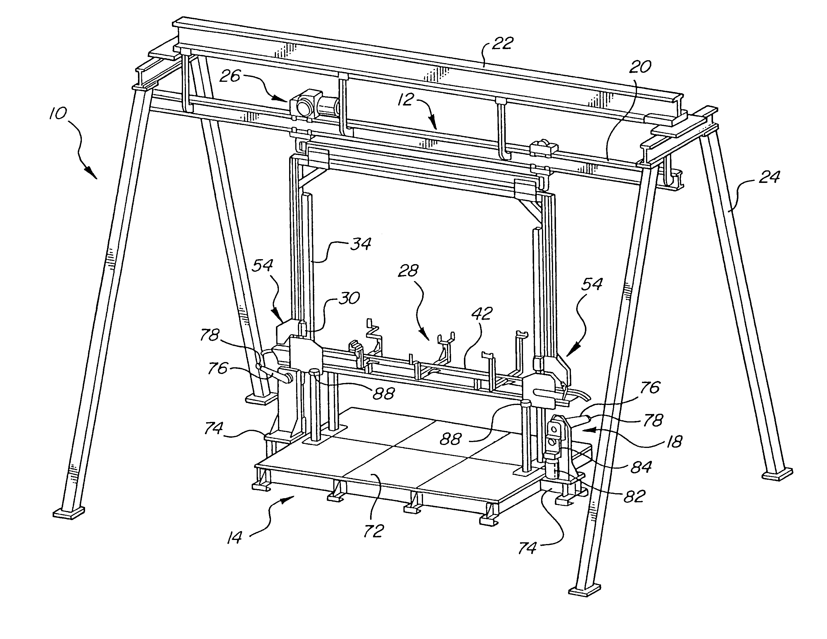
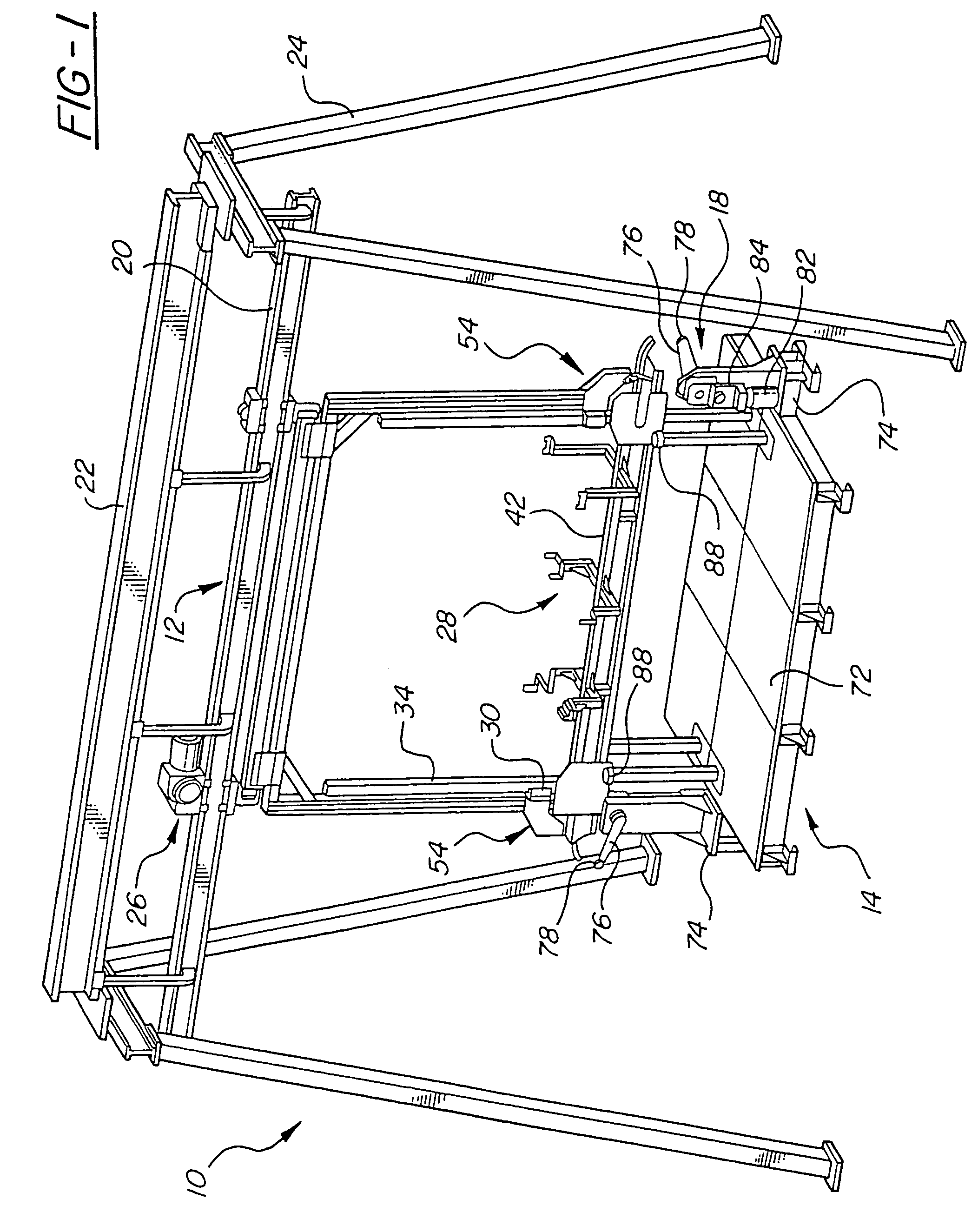
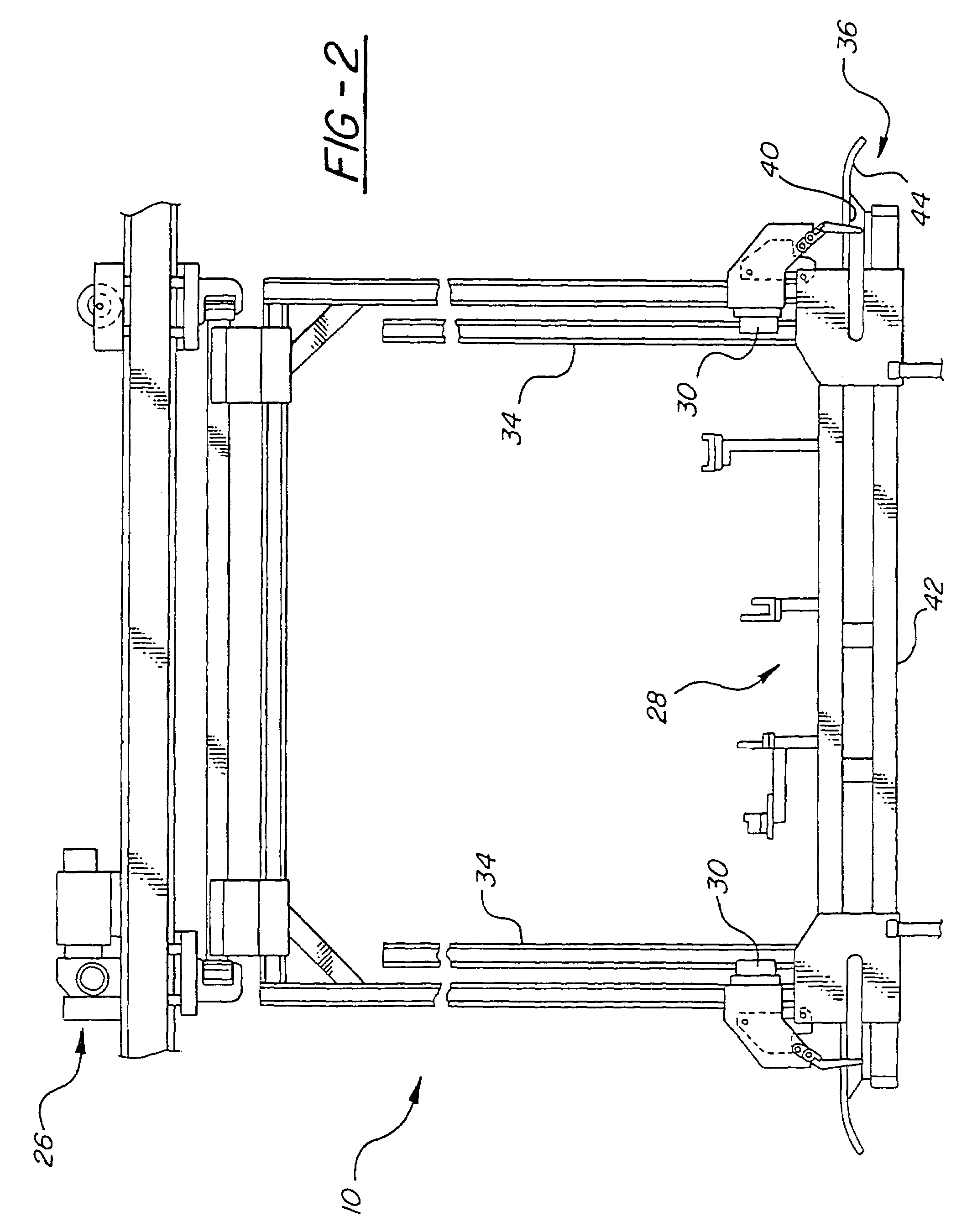
[0006]Preferably, the overhead delivery system for the bodyside left hand assembly line, the bodyside right hand assembly line, and the underbody tack workstation is an electric monorail system. The electric monorail system can provide an overhead rail extending between the various workstations, and preferably extends in a circular or loop configuration passing through the workstations and through a workpiece support or antler exchange workstation for preparing the overhead delivery system to receive and transport different body styles or models through the assembly line without any loss of production. The electric monorail system can include a carriage powered by an electric motor for movement between the workstations along the overhead monorail. Downwardly extending supports or pillars extend from the carriage for receiving the workpiece support or antlers there between. The workpiece supports or antlers are interchangeable as required for engaging the particular body style or model of components to be manufactured through the assembly line. The vertically extending supports or pillars include a telescoping function to allow the workpiece support or antlers to be moved from a vertically raised position used to transport the workpiece or components between workstations, and a vertically lowered position at a workstation to deliver the workpiece or a component to the workpiece support, nest or geometry fixture at the particular workstation. The vertically extending supports or pillars also include latching mechanisms to hold the workpiece support or antlers in the raised position during transport between workstations. Preferably, the drive for unlatching and lowering the workpiece support or antlers and supported workpiece or component is provided at each workstation, and includes a single drive for each vertically extending support or pillar of the electric monorail carriage system. Preferably, the single drive for each vertically extending support or pillar of the carriage located at the workstation is capable of unlatching the latch mechanism prior to lowering the workpiece support or antlers at the workstation location, and after the work has been performed at that workstation raising the work support or antler portion of the carriage to the raised position and latching the latch mechanism of the vertically extending support or pillars from the carriage prior to the carriage leaving the workstation.

Problems solved by technology

When this number is multiplied by the number of models to be produced on the assembly line, the number of pallets can be a very large number requiring large amounts of off line storage space and also requiring a tremendous amount of maintenance to maintain the accurate geometry required of a palletized fixture.

Method used


Image

  • Flexible automotive assembly line method
  • Flexible automotive assembly line method
  • Flexible automotive assembly line method

Examples


Embodiment Construction

[0036]Referring now to FIG. 1, the present invention generally includes workpiece conveyance means 10 for transporting a workpiece along path means 12 for defining a path of travel between workstations 14 positioned along the path means, and locator means positioned at the workstation and operative for locating the workpiece at the workstation. A lowerator 18 is provided for moving the workpiece between the conveyance means 10 and the locator means. For purposes of illustration, the lowerator 18 is shown in combination with an assembly system including the path means 12 and workstations 14. The conveyance means 10 transports workpieces between the workstations 14, where one or more specific processing operations are performed on the workpieces. For instance, the assembly system can be in the form of an automotive production line where workpieces, such as automotive body panels and frame components, are progressively assembled at the workstations 14 along the path 12 of travel. While...


PUM


Abstract

An apparatus for assembling an automotive body on an assembly line having a right-hand body subassembly line, a left-hand body subassembly line and an underbody subassembly line, for delivery to a pallet transport system for movement through a body framing subassembly line. The apparatus includes an overhead transport system for transporting automotive components along at least one of the subassembly lines and for conveying the automotive components along a pallet transport system on the body framing subassembly line. The overhead transport system includes a trolley movable along a single overhead rail, a carriage slidably movable relative to the trolley, and a plurality of antler nests. Each antler nest is individually engageable with the carriage. The apparatus also includes a lowerator for transferring components from the overhead transport system to a geometry fixture at a workstation along the subassembly line. The workstation along the subassembly line can include a plurality of geometry fixtures that are exchangeable at a ready position of the workstation.

Description

CROSS REFERENCE TO RELATED APPLICATIONS[0001]This application is a divisional application of U.S. Utility application Ser. No. 10 / 402,901 filed Mar. 28, 2003; now U.S. Pat. No. 6,827,197; Which is a divisional application of U.S. Utility application Ser. No. 09 / 767,931, filed Jan. 23, 2001, for a FLEXIBLE AUTOMOTIVE ASSEMBLY LINE AND METHOD, now U.S. Pat. No. 6,554,119; which was a continuation of U.S. Provisional Patent Application Ser. No. 60 / 180,607, filed Feb. 7, 2000, for a METHOD AND APPARATUS FOR FLEXIBLE BODY ASSEMBLY. U.S. Utility application Ser. No. 09 / 767,931 for a FLEXIBLE AUTOMOTIVE ASSEMBLY LINE AND METHOD was filed contemporaneously with two other applications, U.S. Utility application Ser. No. 09 / 767,929, for a INTERCHANGEABLE NESTS FOR SUPPORTING COMPONENTS ON A TRANSPORT SYSTEM, now U.S. Pat. No. 6,557,690 and U.S. Utility application Ser. No. 09 / 768,090, for a FLEXIBLE AUTOMOTIVE ASSEMBLY WORKSTATION AND METHOD, now U.S. Pat. No. 6,564,440.FIELD OF THE INVENTION[...

Claims


Application Information

Patent Timeline
IPC IPC(8): B65G47/22B62D65/18
CPCB62D65/18
Inventor OLDFORD, KEITH A.DUGAS, MICHAEL R.KILIBARDA, VELIBORKAUFMAN, ALAN S.JOHNSON, KARL G.
Owner COMAU LLC
Learn More