Brake system for braking aircraft wheels

a technology for aircraft wheels and brake systems, applied in noise/vibration control, braking elements, slack adjusters, etc., can solve the problems of low phase delay, high probability of two modes combining into an unstable mode, and unsatisfactory reliability of the solution

Inactive Publication Date: 2006-10-24
SAFRAN LANDING SYSTEMS
View PDF9 Cites 9 Cited by
  • Summary
  • Abstract
  • Description
  • Claims
  • Application Information

AI Technical Summary

Benefits of technology

[0008]An object of the present invention is to design a brake system which is also organized to obtain different characteristic modes, which is, in particular favorable for withstanding the whirl deformation which is encountered in brake structures both in the axles and in the structures surrounding said axles.

Problems solved by technology

In addition, the structure which surrounds the axle is also subjected to flexing forces of the same type, generating dynamic deformations of the same type, which deformations take place with a small amount of phase delay relative to the deformations of the axle.
The two coupled modes combine to generate an unstable mode, and specialists know that if the two modes have frequencies that are close to each other, the probability of the two modes combining into an unstable mode is high.
However, in addition to being complex, such a solution is unsatisfactory in terms of reliability, in particular in the event of hydraulic failure.
However, in that approach, it is extremely difficult to control the stiffnesses reliably in different directions.
However, such an approach suffers from the drawback of weakening the transverse annular web.
In addition, modifying radial stiffnesses also induces a modification in axial stiffness, which is also unfavorable structurally.

Method used


Image

  • Brake system for braking aircraft wheels
  • Brake system for braking aircraft wheels
  • Brake system for braking aircraft wheels

Examples


Embodiment Construction

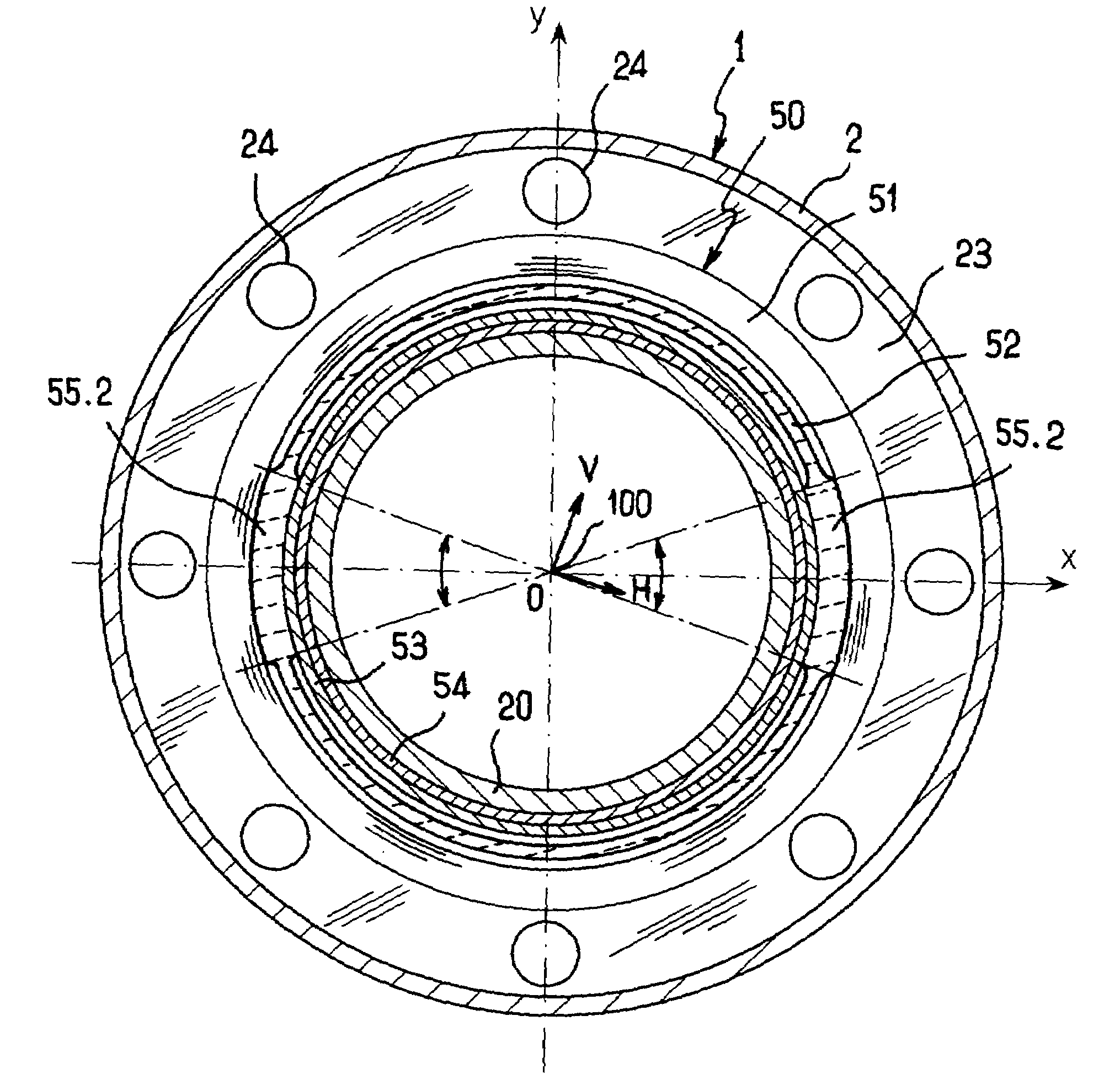
[0026]FIG. 1 shows an aircraft brake unit F comprising a central stator portion 1 which has an axis 100 and which includes a torsion tube 2 to the front of which a brake collar or the like 3 is fixed, e.g. by means of bolts 4 that are screwed into an end collar 5 of said torsion tube. Said brake collar may be of the hydraulic or the electrical type, and, in this example it is equipped with a set of pistons 7 capable of traveling over a predetermined wear stroke by means, for example, of an integrated wear take-up system. Each piston, referenced 10, also serves to transmit the braking forces, the axis of the piston assembly 7 shown being referenced 15.

[0027]The stator central portion 1 coaxially surrounds a wheel axle 20 on which a rotor annular portion 16 is mounted to rotate. For example, as is frequent, it is possible to make provision for the rotor portion 16 to be made up of two adjoining components 16.1, 16.2 united by bolts 17, to form a wheel rim. The rotor annular portion 16...


PUM


Abstract

The invention relates to a brake system for braking aircraft wheels, the brake system being of the type which, for each wheel, comprises a stator central portion coaxially surrounding a wheel axle on which a rotor annular portion is mounted to rotate, and a succession of brake disks disposed between the stator central portion and the rotor annular portion with alternate disks being constrained to rotate with one and the other of said portions, said stator central portion being provided with a brake collar equipped with a plurality of sets of pistons and, rigidly secured to said collar, a torsion tube internally provided with a transverse annular web, a centering bearing being interposed between the annular web and the axle. According to the invention the centering bearing has structural characteristics that vary circumferentially in a distribution configuration suitable for generating different bearing stiffnesses along two orthogonal axes contained in a plane that is perpendicular to the axis of the axle.

Description

FIELD OF THE INVENTION[0001]The present invention relates to a brake system for braking aircraft wheels, the brake system being of the type which, for each wheel, comprises a stator central portion coaxially surrounding a wheel axle on which a rotor annular portion is mounted to rotate, and a succession of brake disks disposed between the stator central portion and the rotor annular portion with alternate disks being constrained to rotate with one and the other of said portions.BACKGROUND OF THE INVENTION[0002]Such brake systems having stacks of disks (generally made of carbon) are in widespread use on aircraft of recent design. Generally, the stator central portion is provided with a brake collar equipped with a plurality of sets of pistons and, rigidly secured to said collar, a torsion tube. The stator portion is supported on the axle in question firstly at the brake collar, and secondly at a transverse annular web present inside the torsion tube. A centering bearing is then inter...

Claims


Application Information

Patent Timeline
Patent Type & Authority Patents(United States)
IPC IPC(8): F16D55/36F16D65/00
CPCF16D55/36F16D65/0006
Inventor SOUETRE, JEANDUROLLET, THOMASDEREURE, OLIVIER
Owner SAFRAN LANDING SYSTEMS
Why Eureka
Try Eureka