
Method and apparatus for measuring phase error of a modulated signal

a modulated signal and phase error technology, applied in the field of frequency shift key (fsk) signal generators, can solve the problems of difficult production of filtering gmsk signals, high cost, and methods developed heretofore that are not suitable for practical application in burst mode, and achieve the effect of reducing the time for hopping

Active Publication Date: 2006-10-17
RADIA COMM
View PDF3 Cites 12 Cited by
  • Summary
  • Abstract
  • Description
  • Claims
  • Application Information

AI Technical Summary

Benefits of technology

[0006]It is therefore an object of the present invention to provide methods and apparatus having high speed automatic calibration loops and feedforward compensation of phase gain and phase preemphasis coefficients for providing precisely shaped frequency transitions between modulation states in a burst mode modulated signal.
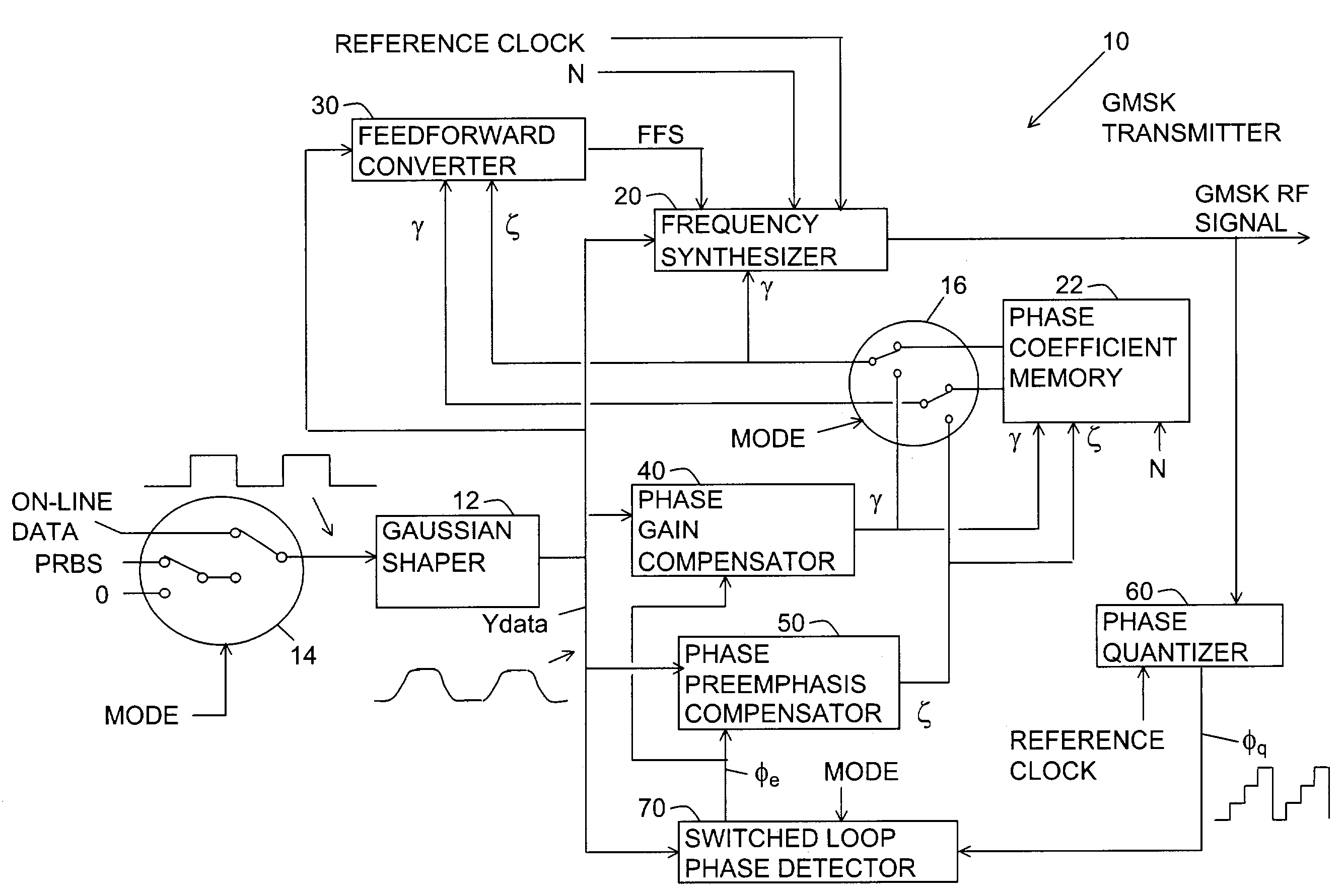
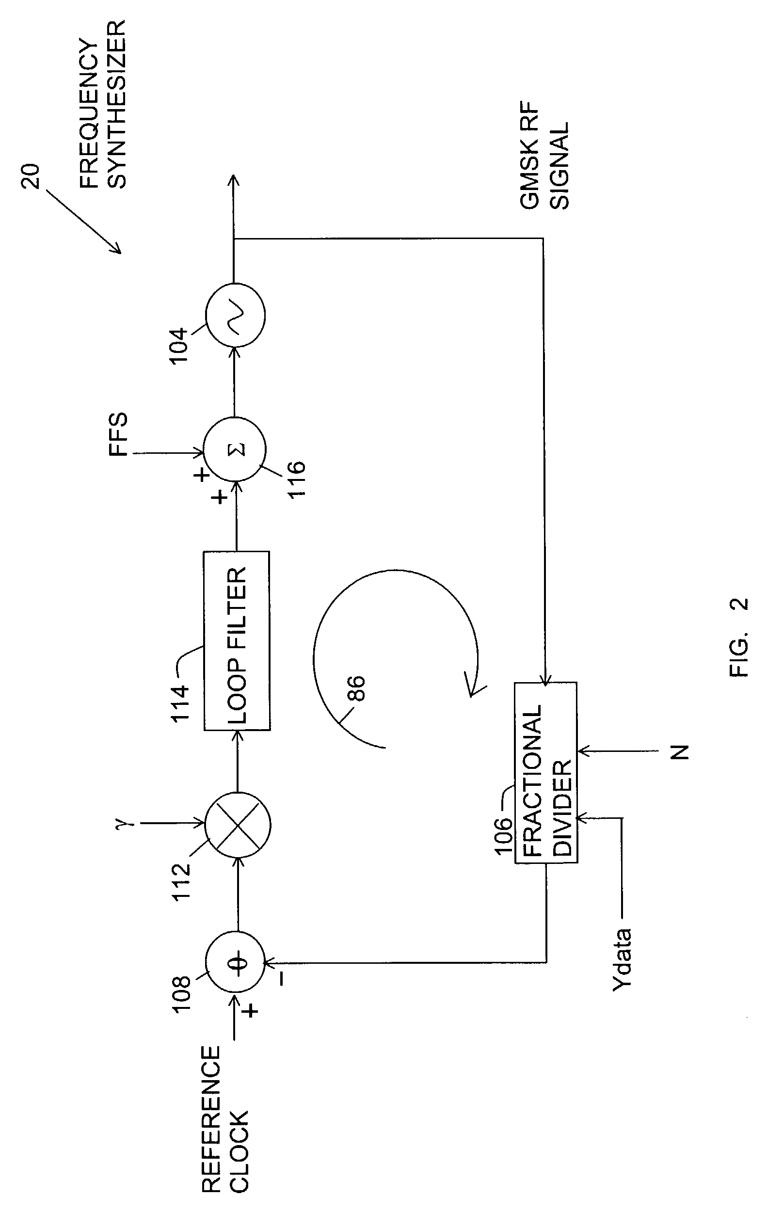
[0007]Briefly, in a preferred embodiment, a transmitter of the present invention includes a Gaussian shaper, a frequency synthesizer, a feedforward converter, a phase gain compensator, a phase preemphasis compensator, a phase quantizer, and a switched loop phase detector. The Gaussian shaper shapes binary input data for providing a digital Gaussian shaped input data signal. The frequency synthesizer uses the shaped input data signal and divide numbers in a frequency synthesis loop for generating a radio frequency (RF) modulated output signal at hopping carrier frequencies in bursts. The synthesis loop includes a voltage controlled oscillator (VCO). Inside the bandwidth of the synthesis loop, the modulation is controlled by the synthesis loop. Outside the bandwidth of the synthesis loop, the modulation is controlled by a feedforward signal that couples into the input of the VCO. The feedforward converter provides the feedforward signal by scaling the input data signal with phase gain coefficients corresponding to carrier frequencies and preemphasizing the input data signal with a phase preemphasis coefficient. The coefficients are determined in an initial calibration mode and then re-determined within calibration burst time slots between on-line signal bursts during high speed on-line burst signal communication. The phase gain coefficients are also used in a loop normalizer in the frequency synthesizer for stabilizing the loop gain of the frequency synthesis loop.
[0008]For calibration, the input data signal is a fixed input data signal and then a shaped sequential input data signal. The phase quantizer provides a quantized phase signal for the phase of the RF modulated signal. The switched loop phase detector includes a phase measurement loop for finding a phase calibration that minimizes a phase difference between the quantized phase signal and a fixed input phase signal that is determined from the fixed input data signal. This phase calibration eliminates an unknown erroneous phase offset. Then, the phase measurement loop is opened and the switched loop phase detector uses the phase calibration for calibrating phase of a sequential input phase signal for the sequential input data signal. The calibrated sequential input phase signal is compared to the quantized phase signal for determining measured phase errors.
[0011]With the phase measurement loop open, the phase preemphasis correlator and the preemphasis accumulator act within a preemphasis calibration loop for correlating the predicted phase preemphasis errors with the measured phase errors. The preemphasis calibration loop uses feedback through the feedforward converter, the frequency synthesizer, the phase quantizer and the switched loop phase detector for determining the phase preemphasis coefficient that minimizes the phase preemphasis error correlations.
[0015]In order to reduce time for hopping between carrier frequencies, the loop normalizer uses the phase gain coefficients to normalize a frequency dependent loop gain of the frequency synthesis loop.
[0016]An advantage of the present invention is that modulation in an output signal is precisely calibrated within the time constraints of the burst time slots of a burst mode signal system.

Problems solved by technology

Unfortunately, the filters for providing GMSK signals are difficult to produce and expensive.
Unfortunately, the methods developed heretofore are not suitable for practical application in a burst mode.

Method used


Image

  • Method and apparatus for measuring phase error of a modulated signal
  • Method and apparatus for measuring phase error of a modulated signal
  • Method and apparatus for measuring phase error of a modulated signal

Examples


Embodiment Construction

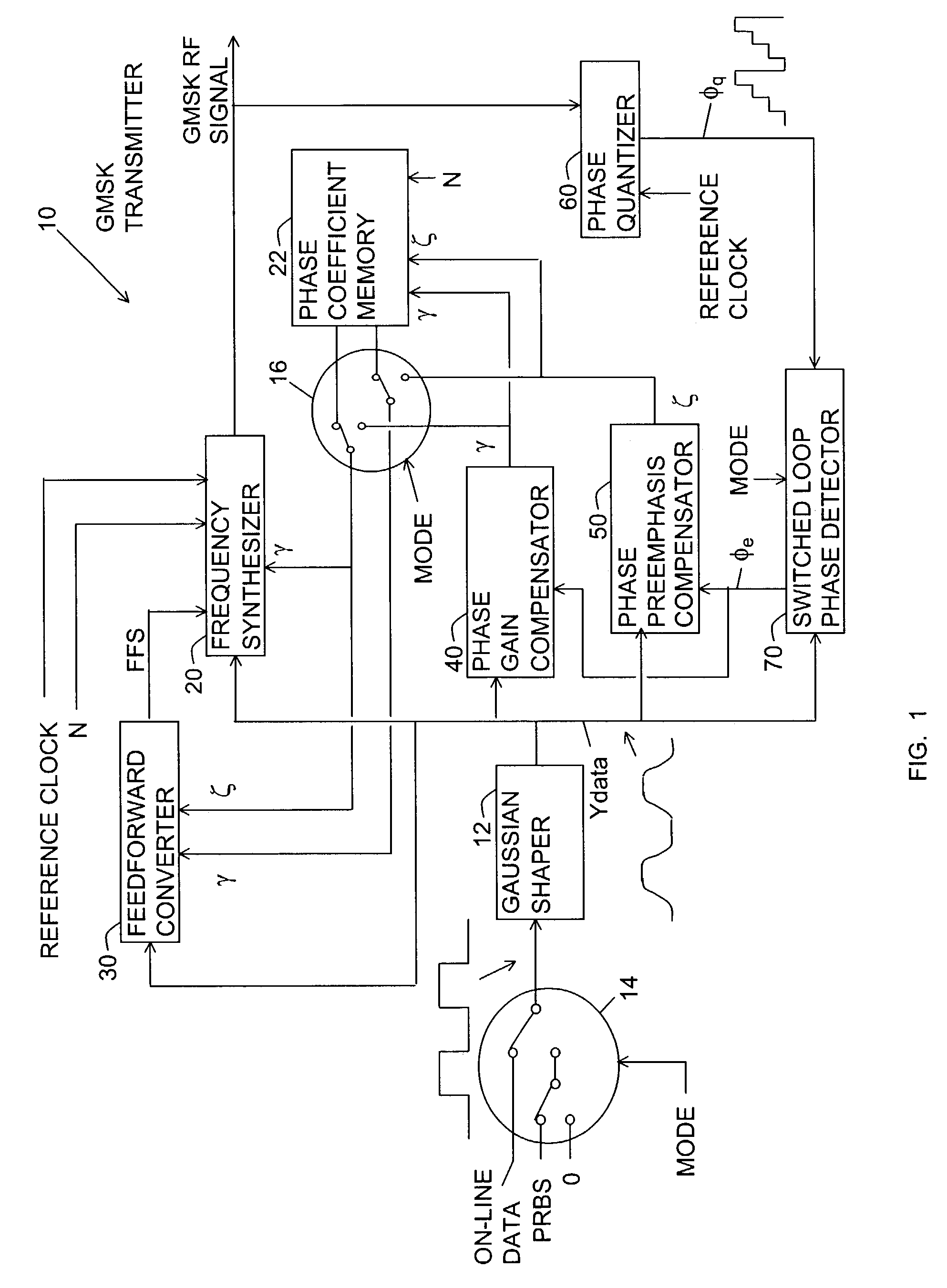
[0034]FIG. 1 is a block diagram of a Gaussian minimum shift key (GMSK) signal generator or transmitter referred to by the general reference number 10 for providing a radio frequency (RF) GMSK frequency modulated output signal. The GMSK transmitter is described herein as adapted for the Global System for Mobile Communications (GSM). However, the idea of the GMSK transmitter 10 of the present invention can be applied to other systems where the accuracies of the modulation states and the paths of the transitions between the modulation states is important. GSM is also known as Groupe Speciale Mobile.

[0035]The GMSK transmitter 10 includes a Gaussian input data shaper 12, an input mode switch 14, an output mode switch 16, a frequency synthesizer 20, a phase coefficient memory 22, a feedforward converter 30, a phase gain compensator 40, a phase preemphasis compensator 50, a phase quantizer 60, and a switched loop phase detector 70.

[0036]The GMSK transmitter 10 has two modes: a calibration ...


PUM


Abstract

A method and apparatus for generating a burst FSK signal having precisely shaped transitions between modulation states. The apparatus uses feedforward compensation of phase gain and phase preemphasis coefficients for compensating the frequency conversion gain of the apparatus, and the phase gain coefficient is used for stabilizing a frequency synthesis loop. The phase gain and preemphasis coefficients are determined in a calibration within the time constraints of on-line signal bursts based upon measured phase errors and accelerated predicted phase gain and preemphasis phase errors.

Description

BACKGROUND OF THE INVENTION[0001]1. Fields of the Invention[0002]The invention relates generally to frequency shift key (FSK) signal generators and more particularly to an FSK generator having high speed automatic calibration loops for determining phase gain and phase preemphasis correction coefficients and then using feedforward compensation for providing precisely shaped frequency transitions between modulation states in a burst mode modulated signal. The invention also relates particularly to a frequency hopping signal generator using phase gain coefficients for stabilizing loop gain of a frequency synthesis loop. The invention also relates particularly to an apparatus and a method for dynamic measurement of phase error of a modulated signal.[0003]2. Description of the Prior Art[0004]Minimum frequency shift key (MSK) modulation is commonly used in modern communication systems. In order to meet regulations for spectrum management, existing systems use filters for softening the tra...

Claims


Application Information

Patent Timeline
Patent Type & Authority Patents(United States)
IPC IPC(8): H04L27/12H03C3/09H03D13/00
CPCH03C3/0925H03C3/0933H03C3/0941H03C3/095H03C3/0975H03C3/0983H03C3/0991H03D13/005
Inventor BROWN, JAMES E. C.ROTHENBERG, BRET
Owner RADIA COMM
Learn More