
Assembly and method for determining speed of a supercavitating underwater vehicle

a supercavitating underwater vehicle and speed measurement technology, applied in the direction of special-purpose vessels, vessel construction, instruments, etc., can solve the problems of inapplicability of vehicle control systems, inability to respect cavity formation means and vehicle control systems, and inability to use the cavitator surface as a velocity sensor

Inactive Publication Date: 2006-10-17
THE UNITED STATES OF AMERICA AS REPRESENTED BY THE SECRETARY OF THE NAVY
View PDF6 Cites 28 Cited by
  • Summary
  • Abstract
  • Description
  • Claims
  • Application Information

AI Technical Summary

Benefits of technology

[0015]The above and other features of the invention, including various novel details of construction and combinations of parts and method steps, will now be more particularly described with reference to the accompanying drawings and pointed out in the claims. It will be understood that

Problems solved by technology

The optimal use of this small wetted contact area presents problems with respect to cavity formation means and vehicle control systems, all of which must be disposed in this limited space.
However, in supercavitating vehicles, the use of the cavitator surface as a velocity sensor is impractical.
Further, the lack of wetted contact areas means traditional methods of using dynamic fluid pressure for determining speed are not practical.
In as much as supercavitating vehicle technology is in its early stages of development, a complete understanding of vehicle propulsion and hydrodynamics is insufficient to determine vehicle velocity from on-board sensing of fuel consumption, ventilation gas flow rates, and the like.

Method used


Image

  • Assembly and method for determining speed of a supercavitating underwater vehicle
  • Assembly and method for determining speed of a supercavitating underwater vehicle
  • Assembly and method for determining speed of a supercavitating underwater vehicle

Examples


Embodiment Construction

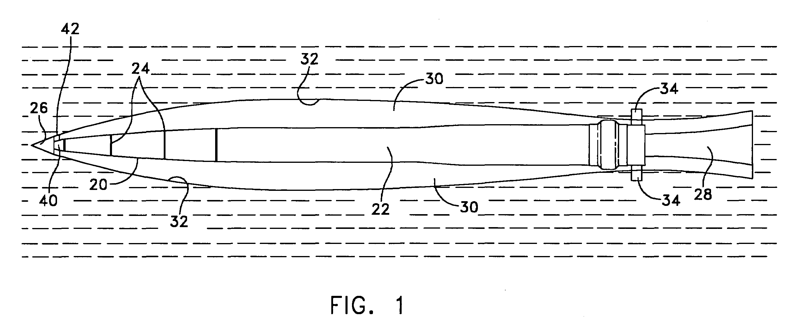
[0022]Referring to FIG. 1, it will be seen that an illustrative underwater vehicle 20 includes an elongated hull 22 of circular cross section. The hull is provided with peripheral grooves or apertures 24 for venting gas, typically air, stored in the vehicle under pressure. The hull 22 is provided with a cavitator, shown herein as a pointed nose cone 26, at the forward end of the hull. The hull 22 contains a reservoir of gas (not shown) under pressure for venting through the grooves 24, and a jet engine (not shown) for propelling the hull 22 forward at a rapid rate. The aft end 28 of the hull 22 is open to accommodate a jet plume when the jet engine is in operation.

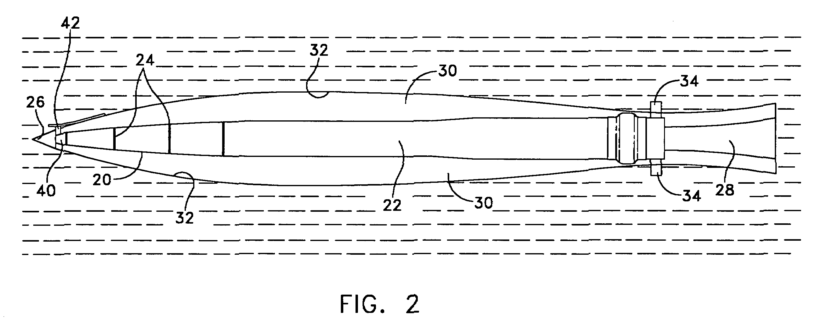
[0023]Referring to FIG. 2, it will be seen that the forward movement of the vehicle 20 causes the nose cone 26, which acts as a cavitator, to create a cavity 30, or vapor region, behind the cone 26. The outflow of pressurized gas from the grooves 24 enlarges the cavity 30 and maintains the cavity such that the water-gas in...


PUM


Abstract

An assembly for determining speed of a supercavitating underwater vehicle during underwater travel includes a fin mounted on the vehicle aft of a cavitator portion of the vehicle and adapted to be extended outwardly beyond a hull of the vehicle and through a boundary of a gas-filled cavity around the vehicle to form a disturbance in the cavity boundary, which disturbance propagates along the boundary. An acoustic transmitter is mounted on the vehicle and directs acoustic energy toward the boundary and the disturbance. An acoustic receiver is mounted on the vehicle and receives acoustic energy reflected off the disturbance. An autopilot is mounted on the vehicle and clocks times of projection of the fin and acoustic transmission receptions of reflected acoustic energy to determine the speed of the vehicle through the water.

Description

STATEMENT OF GOVERNMENT INTEREST[0001]The invention described herein may be manufactured and used by or for the Government of the United States of America for Governmental purposes without the payment of any royalties thereon or therefore.CROSS REFERENCE TO OTHER RELATED APPLICATIONS[0002]Not applicable.BACKGROUND OF THE INVENTION[0003](1) Field of the Invention[0004]The invention relates to high-speed underwater vehicles and is directed more particularly to supercavitating vehicles that move in a cushion of air underwater, and to an on-board assembly and method for measurement of the speed of the vehicle through a water environment.[0005](2) Description of the Prior Art[0006]Recent investigations into high speed underwater vehicles have focused attention on providing vehicles that ride in a cushion of air to achieve high speeds in water. For a nominal prior art streamlined, fully wetted underwater vehicle, 70% of the overall drag is skin friction drag, the remainder is pressure or ...

Claims


Application Information

Patent Timeline
IPC IPC(8): G01S15/60
CPCF42B10/42F42B19/36F42B35/00G01P5/245G01S15/60B63B1/38B63B2001/382B63G8/00Y02T70/122Y02T70/10
Inventor KUKLINSKI, ROBERT
Owner THE UNITED STATES OF AMERICA AS REPRESENTED BY THE SECRETARY OF THE NAVY
Learn More