
Method and system for clock drift compensation

a clock and drift compensation technology, applied in the field of clock drift compensation, can solve the problems of drift, one or more congestion or lack of samples, and considerable residual echo

Active Publication Date: 2009-07-23
CISCO TECH INC
View PDF8 Cites 34 Cited by
  • Summary
  • Abstract
  • Description
  • Claims
  • Application Information

AI Technical Summary

Benefits of technology

[0036]Consequently, at least one aspect of the present invention is to provide a device and method that solves at least one of the above-mention problems with conventional systems.

Problems solved by technology

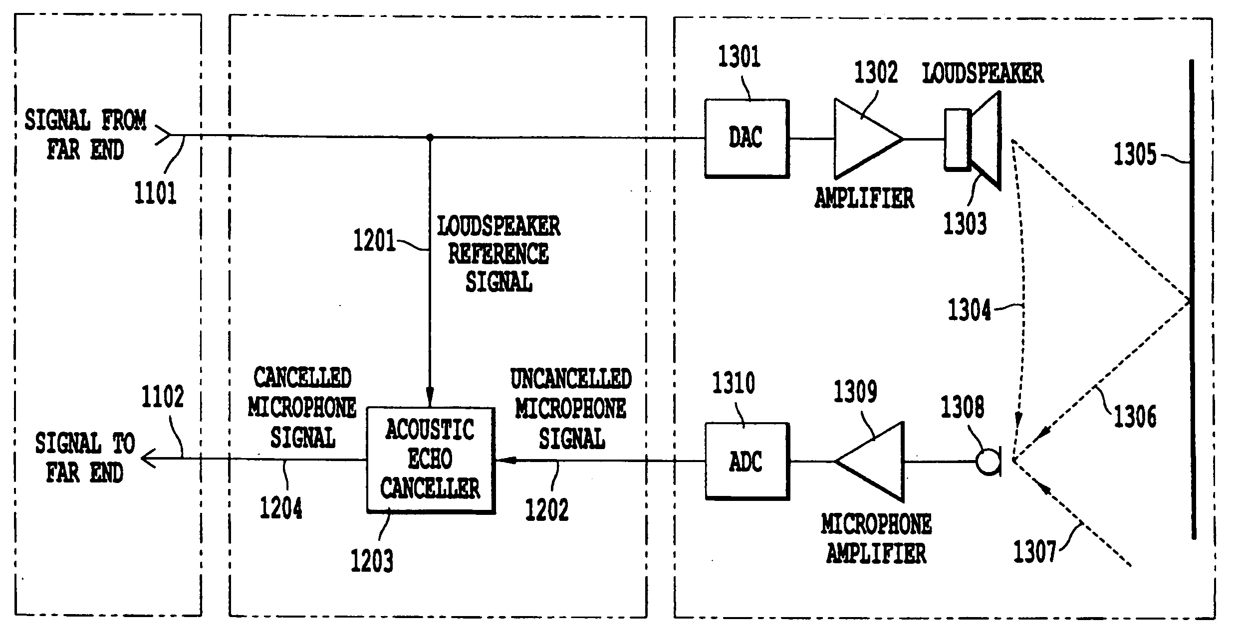
Therefore, although the time delay changes slowly, the effective time shift in response after a period of silence (low 2102 / 3102 power) can be sufficiently big to result in considerable residual echo.3. Overproduction / underproduction of samples: Since the production of samples for the A / D converter differs from the consummation from the D / A converter, there may be a congestion or lack of samples one or more places in the system.
Drift can also occur due to incompatible sample rates.
However, this sample rate converter may have a limited resolution, and thus the nominal sampling frequency will vary.

Method used


Image

  • Method and system for clock drift compensation
  • Method and system for clock drift compensation
  • Method and system for clock drift compensation

Examples


Embodiment Construction

[0047]In the following, aspects of the present invention will be discussed by describing example embodiments, and by referring to the accompanying drawings. However, people skilled in the art based on the teachings herein will realize other applications and modifications within the scope of the invention as defined in the enclosed independent claims.

[0048]A common feature of the several embodiments is a clock drift compensator for computational units such as PCs, compensating for different sampling frequencies in analog to digital (A / D) and digital to analog (D / A) converters, e.g. in audio I / O devices connected to or included in the computational unit. The need for this compensation is due to the use of different circuit boards (e.g., audio board), that include different clock sources, which may not be, and usually are not, derived from a common source. As such, the clocks drift relative to each other and, unlike custom design circuitry, where it is possible to use a face lock loop ...


PUM


Abstract

Different sampling rates between a playout unit and a capture unit are compensated for via a system, method and computer program product. The playout unit receives samples from a computational unit, and the capture unit sends samples to the computational unit. A playout FIFO buffer operates in a playout time domain, and a capture FIFO buffer operates in a capture time domain. The computational unit is synchronized to a common clock. A first relationship is calculated between the common clock and a playout fifo buffer read pointer, and a second relationship is calculated between the common clock and a capture FIFO buffer write pointer. For each sample in the playout time domain a corresponding sample in the samples from said computational unit is found and sent to the playout FIFO buffer. For each sample in the common clock time domain the corresponding sample in the capture time domain is found and sent to the computational unit.

Description

CROSS REFERENCE TO RELATED APPLICATIONS[0001]This application claims the benefit of U.S. Provisional Application No. 61 / 014,636, filed Dec. 18, 2007, the entire contents of which being incorporated here by reference.BACKGROUND OF THE INVENTION[0002]1. Field of the Invention[0003]The present invention relates to clock drift compensation, and in particular clock drift compensation methods, apparatuses and computer program product for echo cancellers implemented on computer based systems.[0004]2. Discussion of the Background[0005]In a conventional conferencing system or any hands free (e.g. not a handheld telephone held to a person's ear) system, one or more microphones capture a sound wave at a site A, and transforms the sound wave into a first audio signal (i.e., an electric signal that conveys the audio content). The first audio signal is transmitted to a site B, where a television set, or an amplifier and loudspeaker, reproduces the original sound wave by converting the first audio...

Claims


Application Information

Patent Timeline
IPC IPC(8): H04B3/20
CPCH04M9/082
Inventor MARTON, TRYGVE FREDERIKLIEN, TORGEIR GROTHE
Owner CISCO TECH INC
Learn More