
Method of optimizing placement and routing of edge logic in padring layout design

a layout design and edge logic technology, applied in the field of generating chip layout designs, can solve the problems of overwhelming complexity of generating padring layout designs, laborious process, daunting task, etc., and achieve the effect of more tim

Active Publication Date: 2006-10-03
SYNOPSYS INC
View PDF1 Cites 40 Cited by
  • Summary
  • Abstract
  • Description
  • Claims
  • Application Information

AI Technical Summary

Benefits of technology

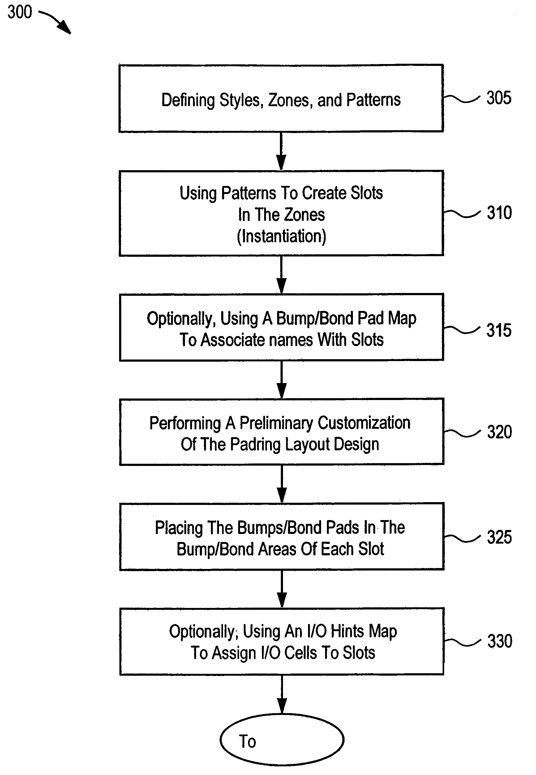
[0011]The variety of problems encountered when laying out padrings are addressed. Automation is emphasized as much as possible so that more time can be used to solve the various problems that make each padring layout design unique. A framework in which regular patterns can be described, replicated, and tailored is provided. The padring is broken down into zones in which slots having bumps / bond pads areas, I / O cell areas, and / or edge logic cell areas are laid out in a regular pattern through an instantiation process. Edge logic, which is comprised of standard cells, is pulled from the core of the chip because these cells couple directly to I / O cells and are critical for timing. The framework allows the bumps / bond pads, I / O cells, and edge logic cells to be laid out in respective bumps / bond pads areas, I / O cell areas, and / or edge logic cell areas according to algorithms associated with the patterns and using a variety of maps which associate the logical netlist with the physical layout design.
[0012]In an embodiment, an editor and a GUI and a perl environment are provided which allow the resulting padring layout to be tailored to handle custom layout or exceptions in the patterns. This provides an environment for generating prototypes quickly to see if a pinout is feasible and determining packaging requirements. The padring layout design is generated in conjunction with package routing / selection and partitioning / floorplanning of the chip so that the chip-package-board system will work together. Finally, patterns can be saved and modified for use with future chips in the same chip family. This allows padring layout designs to be utilized despite shrinking and variability in future chip designs.

Problems solved by technology

When combined with the trend of increasing pin counts, fast clocks, and tight design schedules, the complexity of generating the padring layout design can be overwhelming.
This is often done by hand and can be a laborious process that does not lend itself to making changes in a repeatable manner.
Moreover, laying out a padring with a high pin count, fast clock, low skew, and / or tight design schedule is a daunting task that can occupy a designer for months.
Last minute changes and design schedule pressure can help this problem become a nightmare unless a systematic approach is used.

Method used


Image

  • Method of optimizing placement and routing of edge logic in padring layout design
  • Method of optimizing placement and routing of edge logic in padring layout design
  • Method of optimizing placement and routing of edge logic in padring layout design

Examples


Embodiment Construction

[0054]Reference will now be made in detail to the preferred embodiments of the present invention, examples of which are illustrated in the accompanying drawings. While the invention will be described in conjunction with the preferred embodiments, it will be understood that they are not intended to limit the invention to these embodiments. On the contrary, the invention is intended to cover alternatives, modifications and equivalents, which may be included within the spirit and scope of the invention as defined by the appended claims. Furthermore, in the following detailed description of the present invention, numerous specific details are set forth in order to provide a thorough understanding of the present invention. However, it will be recognized by one of ordinary skill in the art that the present invention may be practiced without these specific details.

Notation and Nomenclature

[0055]Some portions of the detailed descriptions which follow are presented in terms of procedures, lo...


PUM


Abstract

Methods for generating a padring layout design are described. These methods utilize automation while still allowing customization. Automation is emphasized as much as possible so that more time can be used to solve the various problems that make each padring layout design unique. A framework in which regular patterns can be described, replicated, and tailored is provided. The padring is broken down into zones in which slots having bumps / bond pads areas, I / O cell areas, and / or edge logic cell areas are laid out in a regular pattern through an instantiation process. Edge logic, which is comprised of standard cells, is pulled from the core of the chip because these cells couple directly to I / O cells and are critical for timing. The framework allows the bumps / bond pads, I / O cells, and edge logic cells to be laid out in respective bumps / bond pads areas, I / O cell areas, and / or edge logic cell areas according to algorithms associated with the patterns and using a variety of maps which associate the logical netlist with the physical layout design.

Description

RELATED U.S. APPLICATION[0001]This patent application claims priority to the copending provisional patent application Ser. No. 60 / 334,137, entitled “PADRING DESIGN,” and with filing date Nov. 28, 2001. This patent application claims priority to the copending provisional patent application Ser. No. 60 / 352,920, entitled “PADRING GENERATION,” and with filing date Jan. 28, 2002.BACKGROUND OF THE INVENTION[0002]1. Field of the Invention[0003]Embodiments of the present invention generally relate to generating chip layout designs. More particularly, embodiments of the present invention relate to generating the padring layout design.[0004]2. Related Art[0005]Typically, the integrated circuit (or chip) design process begins with a specification which describes the functionality of the chip and may include a variety of constraints. Then, during a logic design phase, the logical implementation of the integrated circuit is determined. Several operations are performed to obtain a logical represe...

Claims


Application Information

Patent Timeline
IPC IPC(8): G06F17/50
CPCG06F17/5072G06F17/5077G06F30/392G06F30/394G06F30/3947
Inventor DAHL, PETER
Owner SYNOPSYS INC
Learn More