
High fidelity, high power switched amplifier

a high-power, switched amplifier technology, applied in the field of magnetic resonance imaging systems, can solve the problems of inability to use these amplifiers, the performance of hybrid designs may be limited by the capabilities of linear amplifiers, and the amplifier design may be quite complex

Active Publication Date: 2006-10-03
GENERAL ELECTRIC CO
View PDF10 Cites 28 Cited by
  • Summary
  • Abstract
  • Description
  • Claims
  • Application Information

AI Technical Summary

Benefits of technology

"The present patent describes a technique for supplying current to a gradient coil in a gradient amplifier power stage. The power stage includes a series coupling of three bridge amplifiers operating at different voltages and the gradient coil. The method includes applying a pulse width modulation scheme to modulate the power applied across the gradient amplifier by each of the three bridge amplifiers. The technical effect of this patent is to provide a more efficient and precise method for supplying current to a gradient coil in a gradient amplifier power stage."

Problems solved by technology

Amplifier designs may be quite complex because the required precision in signals may be less than a milliamp for any current level in the coil current for high performance MRI systems providing quality images.
However, given present power levels, the use of these amplifiers becomes impractical due to the higher voltages and currents.
While there are inherent advantages of such systems, such as the ability to provide higher power levels, the performance of these hybrid designs is limited by the capabilities of the linear amplifiers.

Method used


Image

  • High fidelity, high power switched amplifier
  • High fidelity, high power switched amplifier
  • High fidelity, high power switched amplifier

Examples


Embodiment Construction

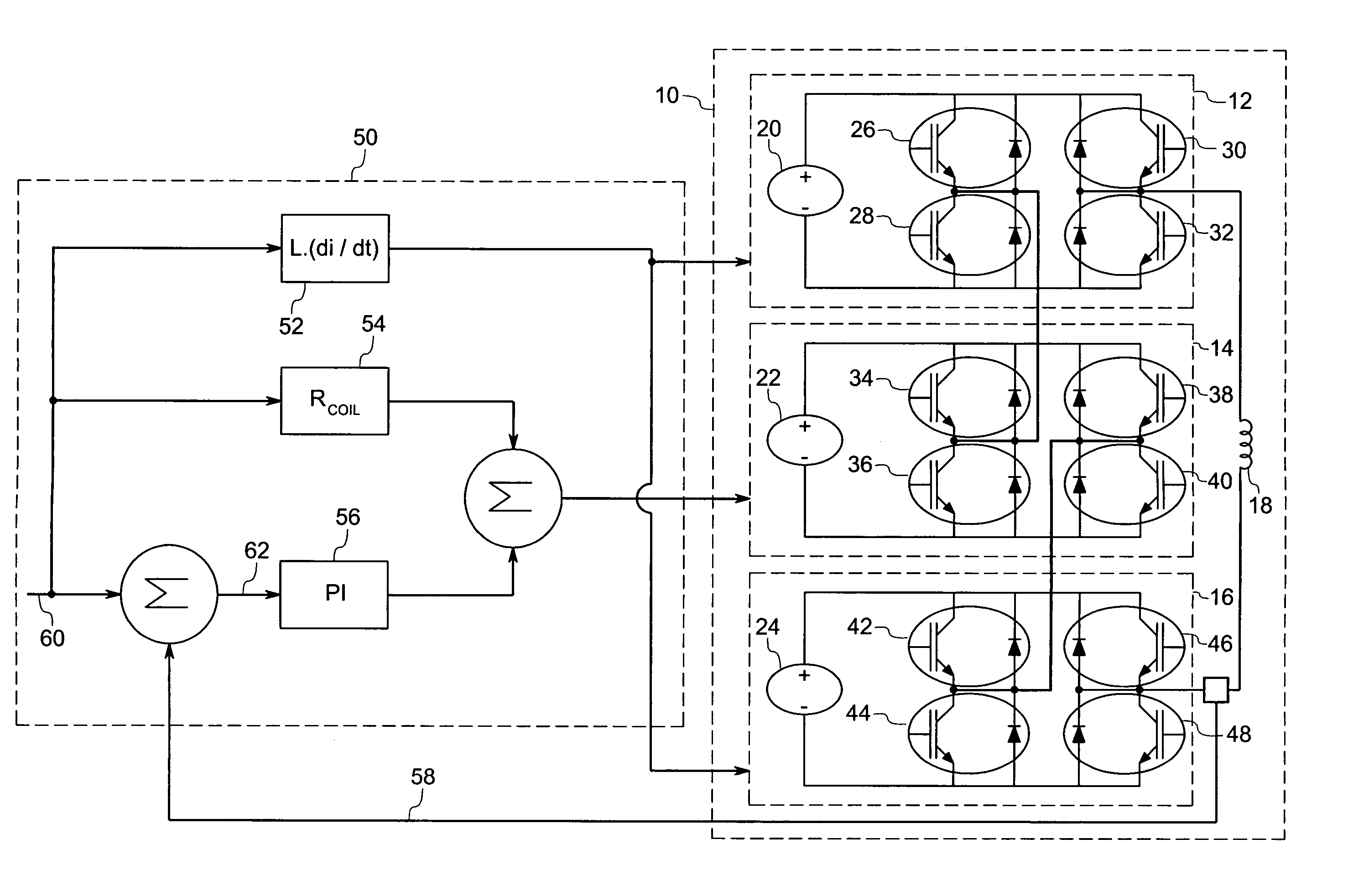
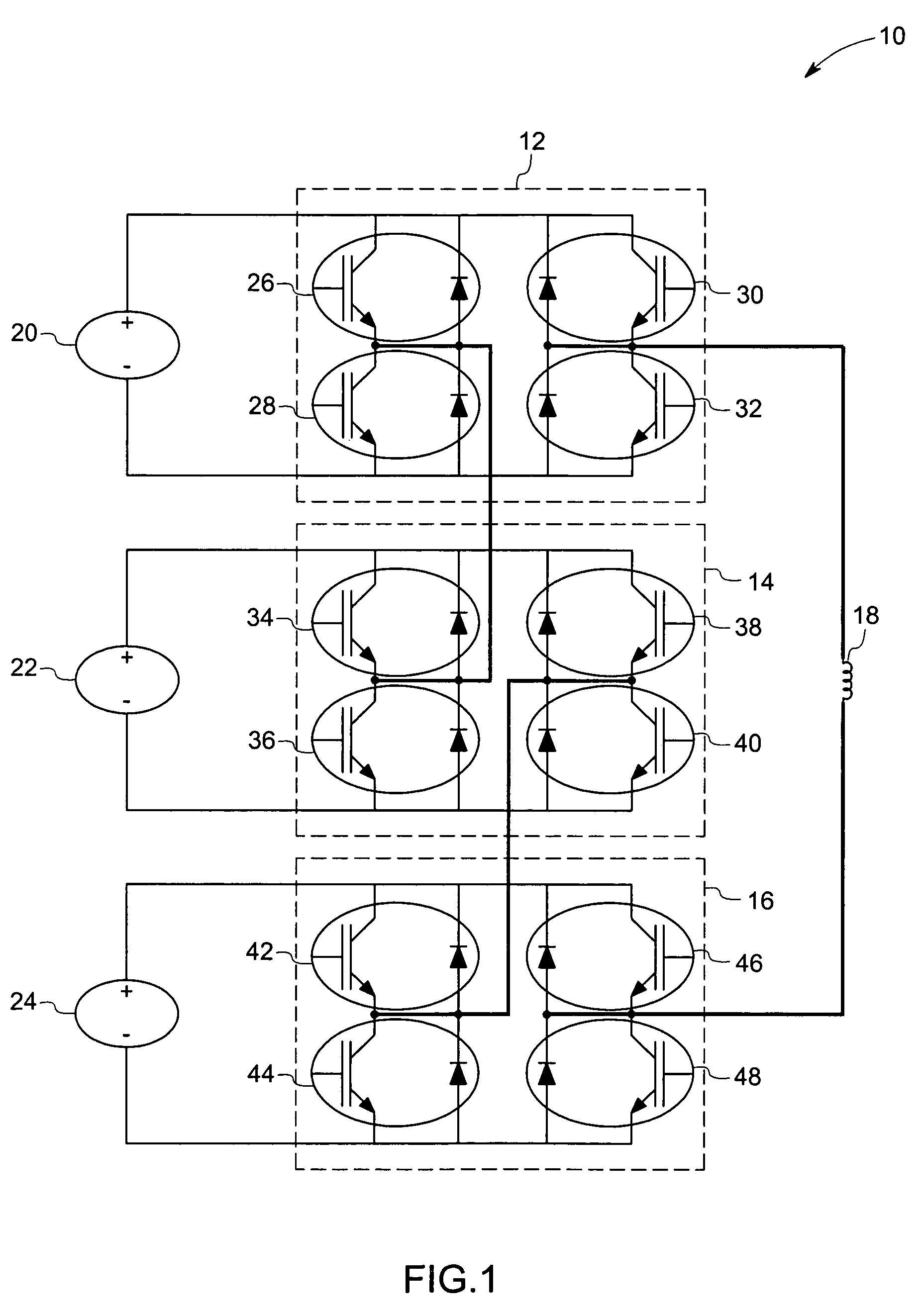
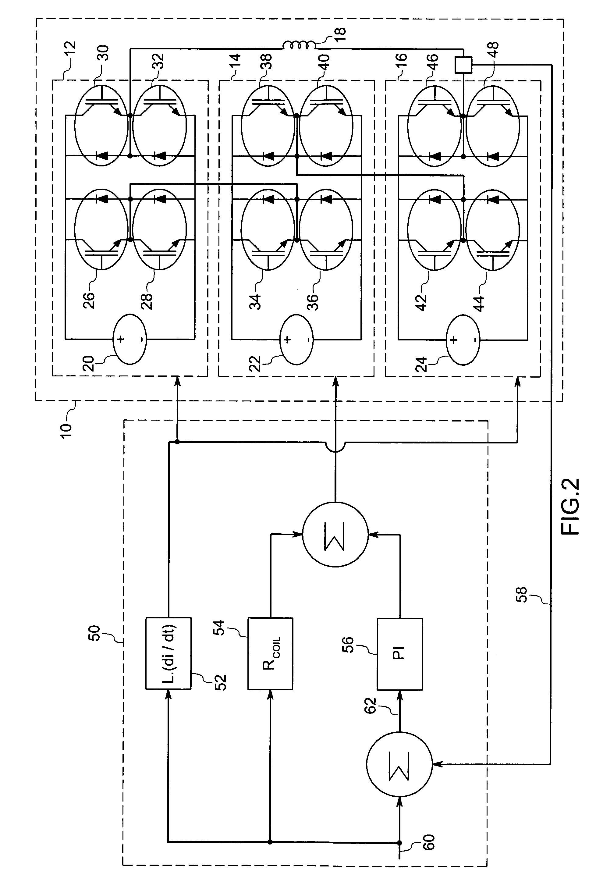
[0023]Turning now to the drawings, and referring first to FIG. 1, an embodiment of a gradient amplifier power stage 10 is represented schematically as comprising a first bridge amplifier 12, a second bridge amplifier 14, a third bridge amplifier 16, a gradient coil 18, a first direct-current (DC) voltage source 20, a second DC voltage source 22, and a third DC voltage source 24. Each component is described in further detail below.

[0024]In the embodiment illustrated in FIG. 1, the first DC voltage source 20 is coupled across the first bridge amplifier 12, the second DC voltage source 22 is coupled across the second bridge amplifier 14, and the third DC voltage source 24 is coupled across the third bridge amplifier 16. Furthermore, the first bridge amplifier 12, the second bridge amplifier 14 and the third bridge amplifier 16 are coupled together in series with the gradient coil 18. The first bridge amplifier 12 further comprises transistor modules 26, 28, 30 and 32. Transistor module...


PUM


Abstract

A gradient amplifier arrangement is described that comprises a gradient amplifier power stage. The device may be employed to provide a current to a gradient coil, as in a MRI system. The circuitry disclosed includes a series coupling of a first bridge amplifier operating at a first voltage, a second bridge amplifier operating at a second voltage, a third bridge amplifier operating at a third voltage, and a gradient amplifier control stage. The amplifiers may provide output voltages at different levels, and may be switched at different times and frequencies to provide a range of output voltage and current levels.

Description

BACKGROUND[0001]The invention relates generally to magnetic resonance imaging systems (MRI) and more specifically to switching amplifiers adapted for use in MRI systems.[0002]A conventional MRI device establishes a homogenous magnetic field generally along a central axis of a subject that is to undergo an MRI procedure. This homogeneous magnetic field affects gyro magnetic material of the subject for imaging by aligning the nuclear spins (in atoms and molecules forming the body tissue in medical applications, for example) along the direction of the magnetic field. If the orientation of the nuclear spins is perturbed out of alignment with the magnetic field, the nuclei attempt to realign their spins with the field. Perturbation of the orientation of nuclear spins is typically caused by application of radio frequency (RF) pulses tuned to the Larmor frequency of the material of interest. During the realignment process, the nuclei precess about their axes of and emit electromagnetic sig...

Claims


Application Information

Patent Timeline
Patent Type & Authority Patents(United States)
IPC IPC(8): H03F3/00H03F3/217G01R33/385G01V3/00H03F1/02H03F3/21H03F3/72
CPCG01R33/3852H03F1/0277H03F3/211H03F3/2173H03F3/2178H03F3/72
Inventor SABATE, JUAN ANTONIOZHANG, RICHARD S.GARCES, LUIS JOSESZCZESNY, PAUL MICHAELLI, QIMINGWIRTH, WILLIAM FREDERICK
Owner GENERAL ELECTRIC CO
Learn More