
Portable radio apparatus

Inactive Publication Date: 2006-09-26
PANASONIC CORP
View PDF11 Cites 8 Cited by
  • Summary
  • Abstract
  • Description
  • Claims
  • Application Information

AI Technical Summary

Benefits of technology

[0007]Portable radio apparatus according to the invention is portable radio apparatus comprising a radio circuit, a speaker, and a shield member for electromagnetically shielding the radio circuit from the speaker, characterized in that the shield member is provided with ventilation holes having a size that does not affect the shielding performance. Via this configuration, it is possible to let air compressed by the vibration at the rear of the speaker to pass through ventilation holes without reducing the shielding performance inherent to the shield member. Thus it is possible to prevent propagation of an electromagnetic wave from a radio circuit to a speaker and improve the sound quality of the speaker.

Problems solved by technology

In the portable telephone set, it is difficult to reserve a sufficient space at the rear of the speaker because of the high-density install; as a result, full performance of a speaker cannot be obtained.

Method used


Image

  • Portable radio apparatus
  • Portable radio apparatus

Examples


first embodiment

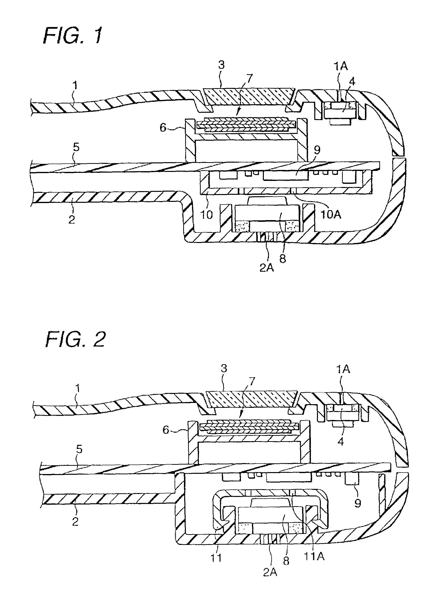
[0011]FIG. 1 is a cross-sectional view of the internal structure of the section above the approximate center of portable radio apparatus according to a first embodiment of the invention.

[0012]The portable radio apparatus comprises a front cover 1 and a rear cover 2 as a casing. On top of the front cover 1 is provided an opening, where a transparent panel 3 for liquid display is fixed. In close proximity of the upper end of the front cover 1, a receiver sound hole 1A is provided. At the position on the inner surface of the front cover 1 corresponding to the receiver sound hole 1A, a receiver 4 is fixed via a cushion. On top of the rear cover 2, a plurality of speaker sound holes 2A are provided. At the position on the inner surface of the rear cover 2 corresponding to the speaker sound holes 2A, a speaker 8 is fixed.

[0013]Within the casing composed of the front cover 1 and the rear cover 2, a printed circuit board 5 is provided. On the upper face of the printed circuit board 5, an LC...

second embodiment

[0017]FIG. 2 is a cross-sectional view of the internal structure of the section above the approximate center of portable radio apparatus according to a second embodiment of the invention. The same components as those in FIG. 1 are given the same signs and the corresponding description is omitted.

[0018]In this embodiment, a holder 11 having a shield feature is provided instead of a shield case 10 in the first embodiment. The holder 11 has a surface composed of for example a metallized resin to shield the speaker 8 from an electromagnetic wave radiated from the radio circuit 9. The holder 11 has a shape that to cover the rear and sides of the speaker 8. In close proximity of the rear of the speaker 8, ventilation holes 11A having a size that does not affect the performance of shielding an electromagnetic wave radiated from the radio circuit 9 are provided. Metallizing a section on the inner surface of the rear cover 2 that faces the radio circuit 9 prevents the electromagnetic wave ra...


PUM


Abstract

A portable radio apparatus has a radio circuit (9) provided on a printed circuit board (5), a speaker (8) provided on a rear cover (2), and a shield case (10) provided to cover the radio circuit (9). In the shield case (10), ventilation holes (10A) having a size that does not affect the shielding performance are provided in close proximity of the rear of the speaker (8).

Description

[0001]This application claims the benefit of International Application Number PCT / JP01 / 02589, which was published in English on Oct. 11, 2001.TECHNICAL FIELD[0002]The present invention relates to portable radio apparatus such as a portable telephone set, and in particular to a portable radio apparatus with improved sound quality of a speaker.BACKGROUND ART[0003]In portable radio apparatus such as a portable telephone set, the casing is getting more and more compact and low-profile in order to enhance portability. Thus, efforts have been made to install in high density a radio circuit, a speaker, a receiver, and an LCD (Liquid Crystal Display) module in a limited space within the casing.[0004]In general, a speaker is easier to vibrate when the volume of a space present at the rear of the speaker is larger. In the portable telephone set, it is difficult to reserve a sufficient space at the rear of the speaker because of the high-density install; as a result, full performance of a spea...

Claims


Application Information

Patent Timeline
IPC IPC(8): H04H1/00H04R1/00H04B1/38H04B1/3822H04M1/02H04M1/03H05K9/00
CPCH04B1/3838H04M1/03H05K9/0041H05K9/0037H05K9/0022
Inventor KUCHIISHI, KOJIINOMATA, YOJIHIGUCHI, TOSHIHIROHAGA, HIDEOISHIHARA, TAKASHI
Owner PANASONIC CORP
Learn More