
Audio signal coding apparatus, audio signal decoding apparatus, and audio signal coding and decoding apparatus

Inactive Publication Date: 2005-03-22
PANASONIC CORP
View PDF7 Cites 82 Cited by
  • Summary
  • Abstract
  • Description
  • Claims
  • Application Information

AI Technical Summary

Benefits of technology

The present invention is made to solve the above-described problems and has for its object to provide an audio signal coding apparatus which efficiently encodes various audio signals at a low bit rate, and with high sound quality, by subjecting the audio signals to adaptive scalable coding as shown in FIG. 13.
According to a thirty-eighth aspect of the present invention, in the audio signal decoding apparatus of the twenty-seventh aspect, the inverse quantization unit performs inverse quantization by using only part of the codes which are output from the audio signal coding apparatus. Therefore, it is possible to realize an audio signal decoding apparatus capable of decoding a coded signal output from an audio signal coding apparatus performing high-quality and high-efficiency adaptive scalable coding in a simple construction.

Problems solved by technology

Therefore, when coding audio signals having various characteristics and distributions, sufficient performance is not exhibited, and high-quality and high-efficiency scalable coding cannot be realized.

Method used


Image

  • Audio signal coding apparatus, audio signal decoding apparatus, and audio signal coding and decoding apparatus
  • Audio signal coding apparatus, audio signal decoding apparatus, and audio signal coding and decoding apparatus
  • Audio signal coding apparatus, audio signal decoding apparatus, and audio signal coding and decoding apparatus

Examples


embodiment 1

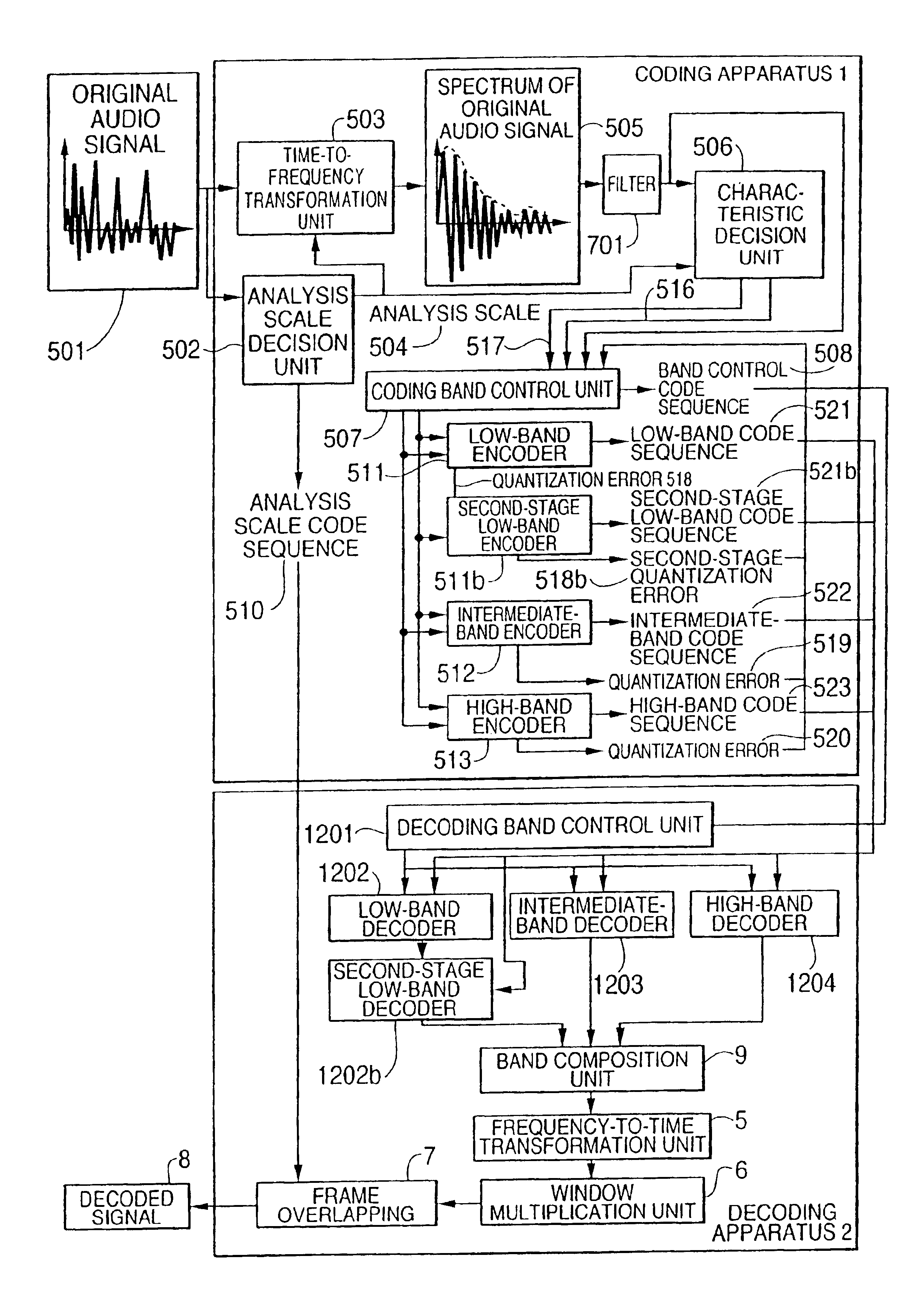
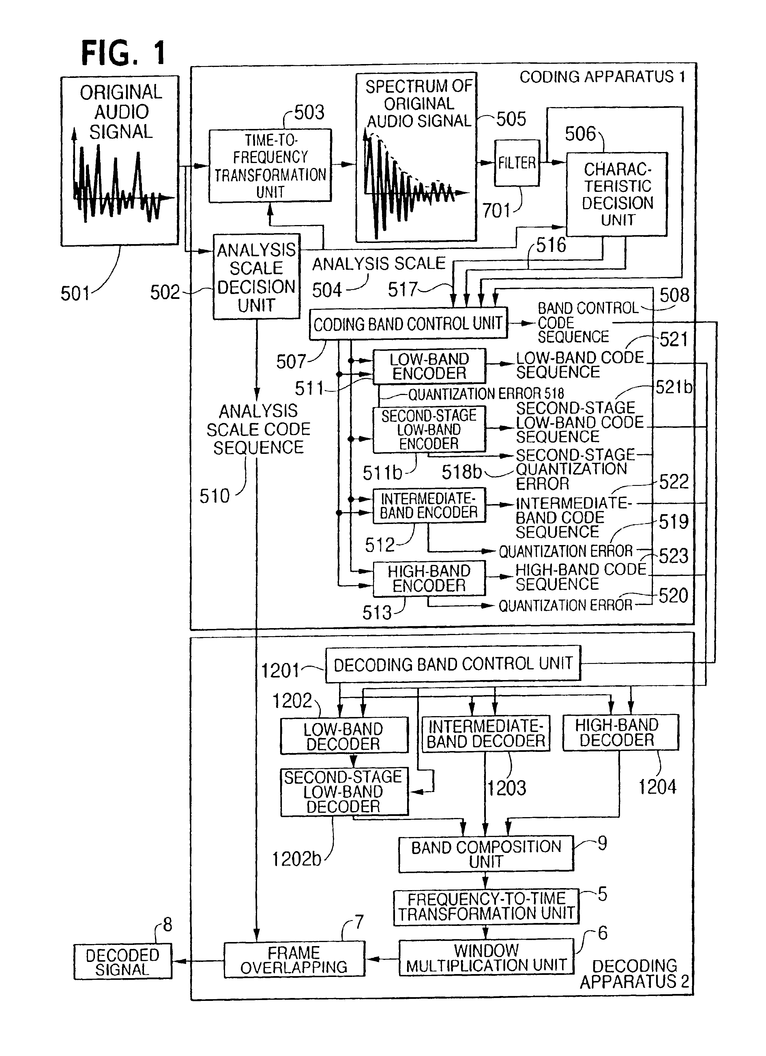
FIG. 1 is a block diagram illustrating an audio signal coding apparatus 1 performing adaptive scalable coding according to a first embodiment of the present invention.

In FIG. 1, reference numeral 1 denotes a coding apparatus for coding an original audio signal 501. In the coding apparatus 1, numeral 502 denotes an analysis scale decision unit which decides an analysis scale 504 for analyzing the original audio signal 501; numeral 503 denotes a time-to-frequency transformation unit which transforms the time axis of the original audio signal 501 to the frequency axis in units of the analysis scales 504; numeral 504 denotes the analysis scale decided by the analysis scale decision unit 502; numeral 505 denotes the spectrum of the original audio signal; numeral 701 denotes a filter to which the spectrum 505 of the original audio signal is input; numeral 506 designates a characteristic decision unit which decides the characteristic of the spectrum 505 of the original audio signal to deci...

embodiment 2

Hereinafter, a second embodiment of the present invention will be described by using FIGS. 14 to 20.

FIG. 14 is a block diagram illustrating a coding apparatus 2001 performing adaptive scalable coding, and a decoding apparatus 2002 adapted to the coding apparatus 2001, according to the second embodiment of the present invention. In the coding apparatus 2001, reference numeral 200105 denotes coding conditions, such as the number of encoders, the bit rate, the sampling frequency of an input audio signal, and the coding band information of each encoder; numeral 200107 denotes a characteristic decision unit which decides the frequency bands of audio signals to be quantized by multiple-stages of encoders; numeral 200109 denotes coding band arrangement information; numeral 200110 denotes a coding band control unit which receives the frequency bands decided by the characteristic decision unit 200107 and the time-to-frequency transformed audio signal, and transforms the quantization bands of...


PUM


Abstract

An audio signal coding apparatus includes a first-stage encoder for quantizing the time-to-frequency transformed audio signal and second-and-subsequent-stages of encoders each for quantizing a quantization error output from the previous-stage encoder A characteristic decision unit is provided which decides the frequency band of an audio signal to be quantized by each encoder of multiple-stage encoders, and a coding band control unit receives the frequency band decided by the characteristic decision unit and the time-to-frequency transformed audio signal, decides the order of connecting the respective encoders, and transforms the quantization bands of the encoders and the connecting order to code sequences. Therefore, it is possible to provide an audio signal coding apparatus performing adaptive scalable coding, which exhibits sufficient performance when coding various audio signals.

Description

FIELD OF THE INVENTIONThe present invention relates to an audio signal coding apparatus which efficiently encodes a signal which is obtained by transforming an audio signal such as a voice signal or music signal by using a method such as orthogonal transformation, so as to represent the same signal with less code sequences relative to the original audio signal, using a characteristics quantity which is obtained from the audio signal itself. The invention also relates to an audio signal decoding apparatus which can decode a high-quality and broad-band audio signal by using all or part of the, code sequences as the coded signal.BACKGROUND OF THE INVENTIONThere have been proposed various methods for efficiently coding and decoding audio signals. Compressive coding methods for audio signals having frequency bands exceeding 20 kHz such as music signals, MPEG audio and Twin VQ (TC-WVQ) have been proposed. In a coding method represented by MPEG audio system, a digital audio signal on a tim...

Claims


Application Information

Patent Timeline
IPC IPC(8): G10L19/00G10L19/02
CPCG10L19/0212H03M7/00
Inventor ISHIKAWA, TOMOKAZUTSUSHIMA, MINEONORIMATSU, TAKESHI
Owner PANASONIC CORP
Learn More