
Method and apparatus for managing tunneled communications in an enterprise network

a communication network and enterprise network technology, applied in the field of communication systems, can solve the problems of complex and time-consuming configuring a network firewall to accept one or more of these protocol signals, tunneling signals will not be permitted beyond the firewall, etc., and achieve the effect of reducing or eliminating at least some of the shortcomings and facilitating tunneling

Inactive Publication Date: 2006-09-19
NISC AFFINEGY LLC
View PDF17 Cites 15 Cited by
  • Summary
  • Abstract
  • Description
  • Claims
  • Application Information

AI Technical Summary

Benefits of technology

[0006]The present invention recognizes a need for a method and apparatus operable to facilitate tunneling in an enterprise network environment. In accordance with the present invention, a system and method for providing enterprise network tunneling are provided that substantially reduce or eliminate at least some of the shortcomings associated with prior approaches.
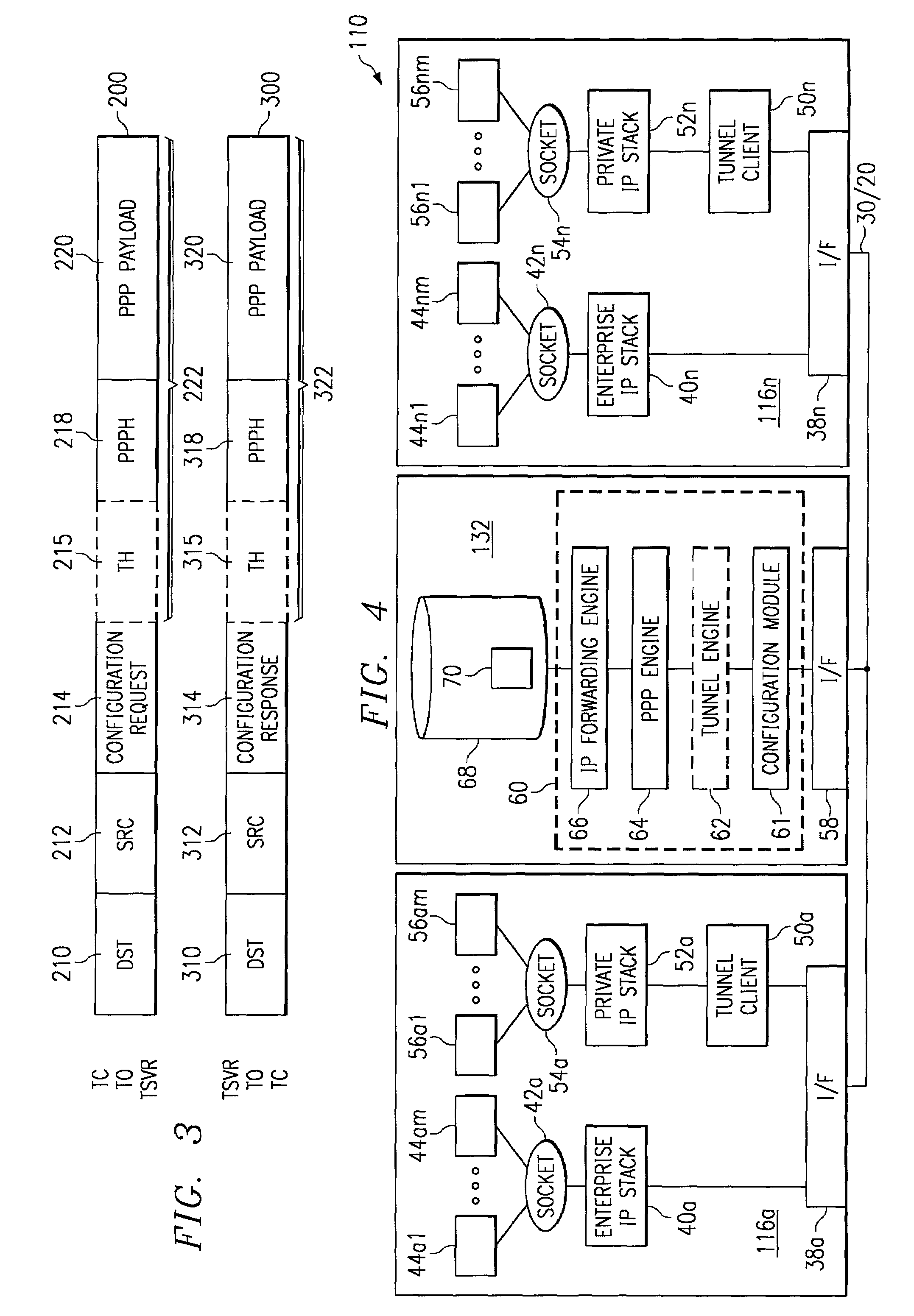
[0011]Depending on the specific features implemented, particular embodiments of the present invention may exhibit some, none, or all of the following technical advantages. One aspect of the present invention provides a method and apparatus operable to facilitate tunneling, particularly in an enterprise network, with a network element that does not have a data channel address. The invention provides a control channel operable to facilitate relaying of configuration protocol encapsulated tunneling signals between network elements, regardless of whether any of those elements has a data channel address. The tunneling signals encapsulated within the configuration protocol headers comprise point-to-point protocol signals carrying any information useful to be supplied to a tunneling server or another tunneling client.
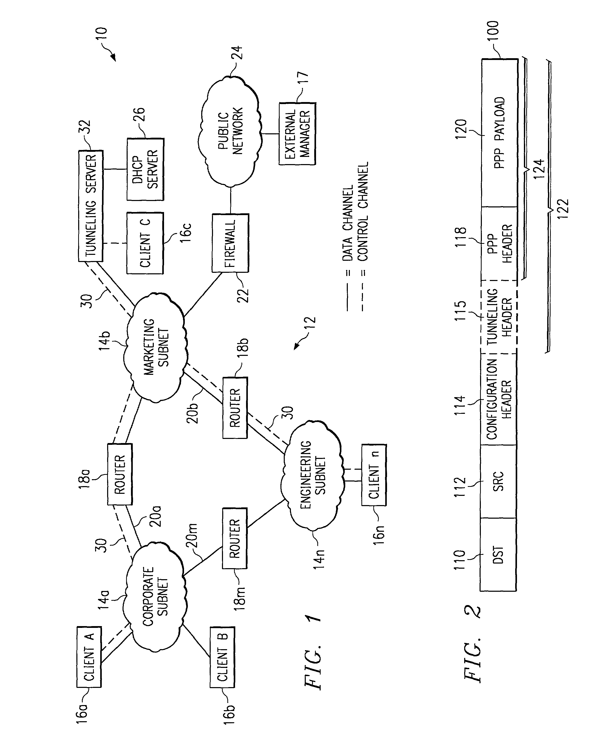
[0012]In a particular embodiment, the tunneling signal encapsulated within the configuration protocol header may comprise a tunneling header appended to the point-to-point protocol signal. The tunneling header may facilitate maintenance of a tunneling session between two network elements using a standard tunneling protocol, such as L2TP, L2F, PPTP, or any other tunneling protocol operable to facilitate a secure connection between network elements. By implementing a tunneling header, this embodiment of the invention can facilitate flow control, authentication, and tunnel identification features available through the various standard tunneling protocols.
[0014]In another aspect of operation, the invention facilitates remote operation of functionality available on one client by another client over the control channel. For example, a first client may communicate commands over the control channel to a second client running a particular application. The second client can receive the command, apply the command to the application to obtain an result, and relay the result back to the first client over the control channel. This feature could apply to any function or process residing on one client, which can be accessed by another client through a control channel.

Problems solved by technology

Used alone, however, these protocols have limitations.
For example, if network firewalls are not specifically configured to accept these tunneling protocols, the tunneling signals will not be permitted beyond the firewall.
Configuring a network firewall to accept one or more of these protocol signals can be complex and time consuming.
As a result, network firewalls are frequently not configured to accept these protocols.
Another problem with using conventional tunneling protocols without modification, which is not solved by the HTTP encapsulation technique, is that network elements without data channel addresses are ineligible to participate in tunneling.
Network elements that do not have data channel addresses recognized by the routers are generally unable to communicate point-to-point protocol signals to other network elements using the routers.
As a result, conventional tunneling protocol signals generally cannot be communicated by or to network elements that do not have a data channel address.
HTTP encapsulation does not address this problem.

Method used


Image

  • Method and apparatus for managing tunneled communications in an enterprise network
  • Method and apparatus for managing tunneled communications in an enterprise network
  • Method and apparatus for managing tunneled communications in an enterprise network

Examples


Embodiment Construction

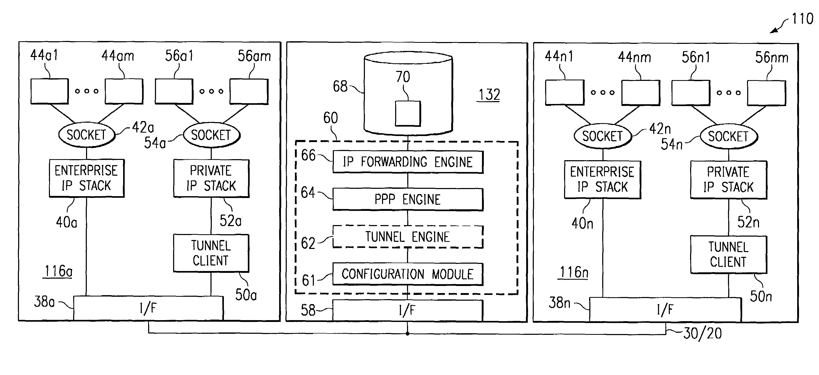
[0025]FIG. 1 is a block diagram of an exemplary embodiment of a system 10 operable to facilitate enterprise network tunneling. System 10 includes an enterprise network 12, which includes a plurality of subnetworks 14a–14n having a plurality of routers 18a–18m coupled between subnetworks 14. Enterprise network 12 may comprise any private network not openly accessible to network elements outside of enterprise network 12. Each subnetwork 14 within enterprise network 12 may comprise any combination of communication links, routers, bridges, switches, or other communication devices operable to facilitate communication between at least a plurality of clients 16 within a common subnetwork 14, and possibly between clients 16 coupled to separate subnetworks 14. Although the illustrated embodiment shows one router 18 between each pair of subnetworks 14, any number of routers 18 and other network equipment could reside between subnetworks 14.

[0026]Enterprise network 12 may be coupled to a publi...


PUM


Abstract

In one aspect of the invention a method includes, at a tunneling server, receiving from first client a point-to-point protocol signal encapsulated within a network address request header, the point-to-point protocol signal comprising an identifier identifying a destination client. The method further comprises encapsulating the point-to-point signal within a network address response header and communicating the network address response encapsulated signal toward the destination client.

Description

[0001]This application is related to pending U.S. application Ser. No. 09 / 726,766, entitled “Method and Apparatus For Tunneled Communication in an Enterprise Network,” which was filed contemporaneously with this application. These applications have been commonly assigned to Efficient Networks, Inc.TECHNICAL FIELD OF THE INVENTION[0002]The present invention relates to the field of communication system,and more particularly to a system and method operable to facilitate management of tunneled communications in an enterprise network.BACKGROUND OF THE INVENTION[0003]Various tunneling protocols exist for facilitating secure connections between network elements. For example, the Layer 2 Tunneling Protocol (L2TP), Layer 2 Forwarding (L2F) Protocol, Point-to Point Tunneling Protocol (PPTP) all provide secure connections between network elements implementing those protocols. Used alone, however, these protocols have limitations.[0004]For example, if network firewalls are not specifically conf...

Claims


Application Information

Patent Timeline
Patent Type & Authority Patents(United States)
IPC IPC(8): G06F15/16H04L29/06H04L29/08H04L29/12
CPCH04L29/06H04L61/2015H04L69/168H04L63/0272H04L69/324H04L69/16H04L61/5014H04L9/40
Inventor DAVIDSON, JOHN M.SUNDARRAJ, AKKAMAPET P.PICKERING, JAMES R.
Owner NISC AFFINEGY LLC
Learn More