
Electroacoustic transducer with a diaphragm, and method for fixing a diaphragm in such transducer

a technology of electroacoustic transducers and diaphragms, which is applied in the direction of diaphragm mounting/tensioning, electric transducers, electrical apparatus, etc., can solve the problems of inability to correct, additional activities and hence additional costs, and achieve the effect of reducing the number of errors, and reducing the number of process steps

Inactive Publication Date: 2006-09-19
SONION NEDERLAND
View PDF21 Cites 24 Cited by
  • Summary
  • Abstract
  • Description
  • Claims
  • Application Information

AI Technical Summary

Benefits of technology

[0013]This embodiment of the invention has the advantage that the connection between the case and the diaphragm can be very elastic and therefore does not deform or tear even in the case of extensive deflections. Also, the attachment is completely free of tension, which is very favorable to the acoustic properties of the diaphragm.
[0017]This second embodiment has the further advantage that the number of process steps is reduced; that errors can more easily be corrected, in particular before the polymer is provided, and that the diaphragm is suspended very flexibly from the circumferential edge, which is connected to the case, so that forming the suspension, as when a film is used, is no longer necessary. Furthermore, in this embodiment, the diaphragms can be manufactured inexpensively in mass production by means of punching. Automatic assembly of the diaphragms is equally possible.

Problems solved by technology

A drawback of all hitherto proposed manners of connecting a diaphragm to the case is the necessity of different production steps, each involving the possible occurrence of errors, which sometimes can and sometimes cannot be corrected, but always entail additional activities and hence additional costs.

Method used


Image

  • Electroacoustic transducer with a diaphragm, and method for fixing a diaphragm in such transducer
  • Electroacoustic transducer with a diaphragm, and method for fixing a diaphragm in such transducer
  • Electroacoustic transducer with a diaphragm, and method for fixing a diaphragm in such transducer

Examples


first embodiment

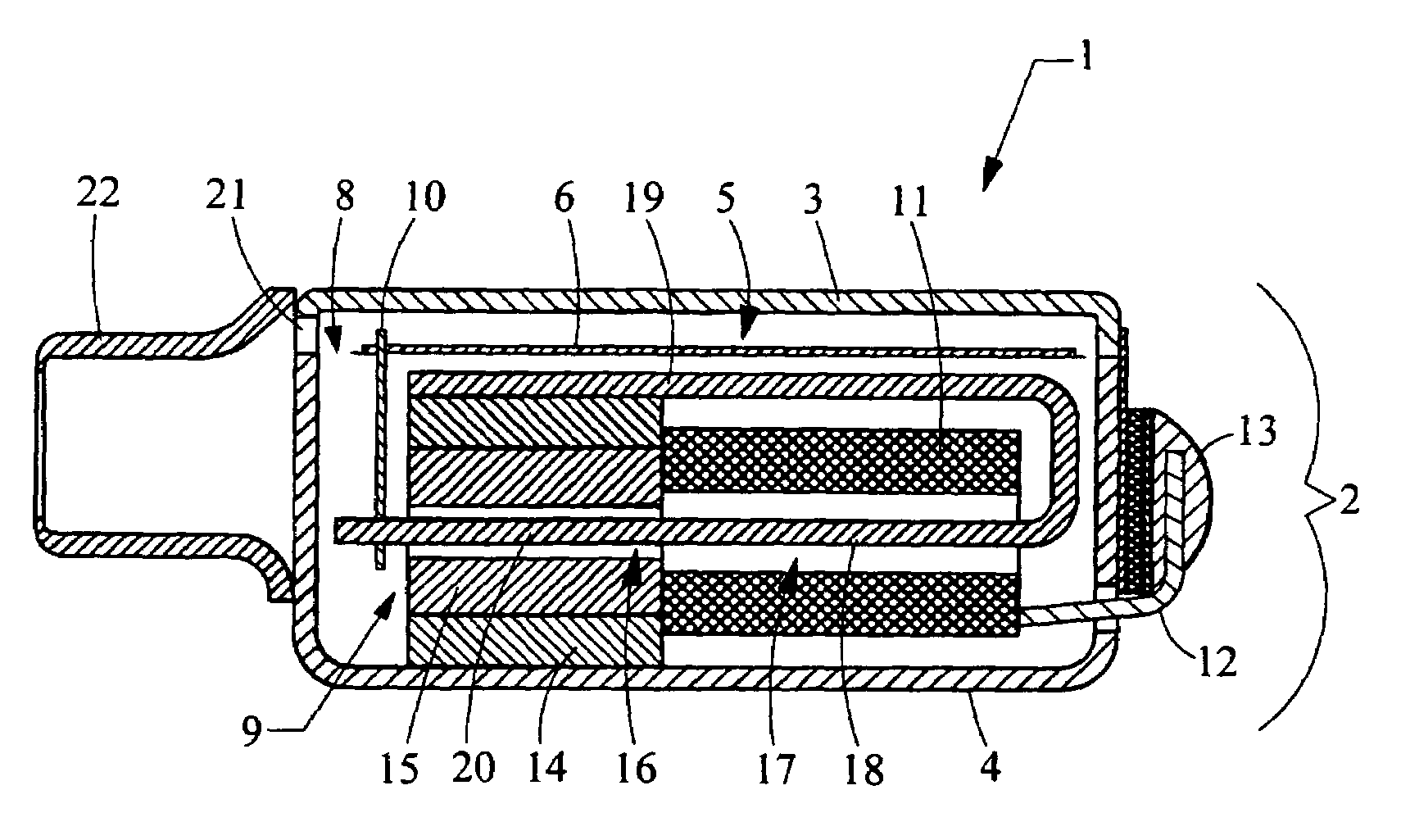
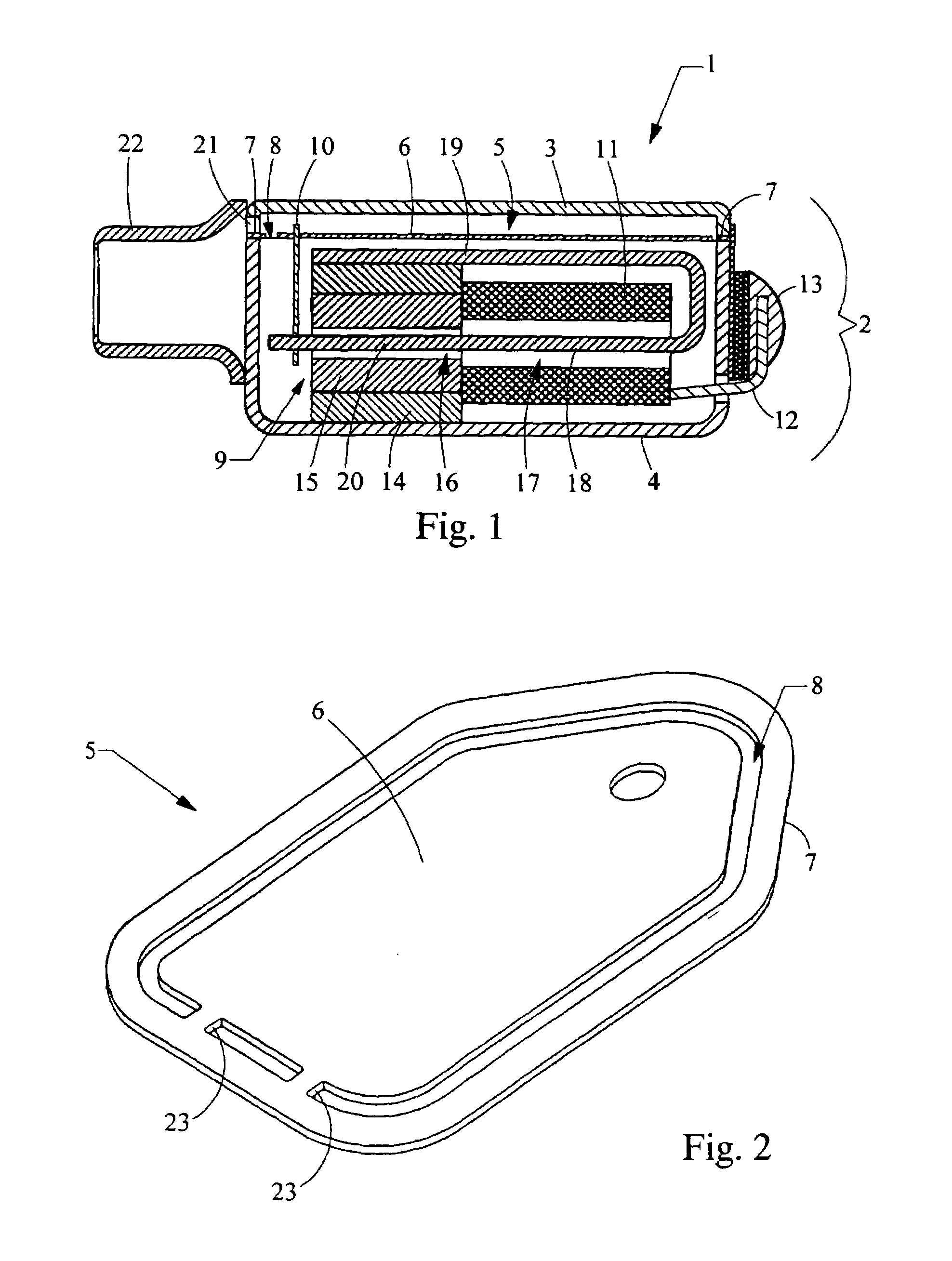
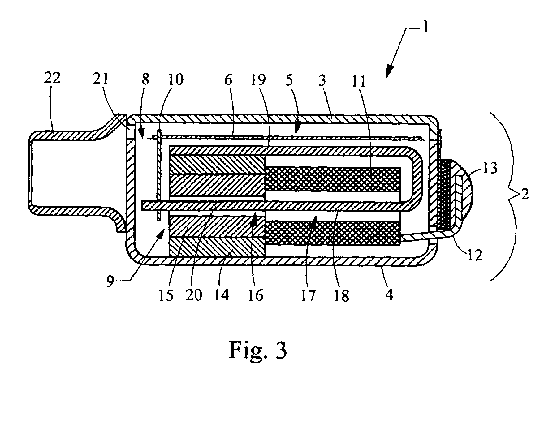
[0033]In the invention, the central diaphragm portion 6 is attached to a film and a polymer is provided in a capillary space between the outer edge of the film and the case wall. This embodiment is shown in FIG. 3, and the construction is virtually the same as that in the construction in FIG. 1, the only difference being that there is no diaphragm portion between the lid and the dish of the transducer case.

second embodiment

[0034]FIG. 2 schematically shows a diaphragm according to the invention, such as it can be applied in the transducer according to FIG. 1. The central diaphragm portion 6 and the circumferential edge 7 are connected to one another by means of one or more connecting strips or bridges 23. The diaphragm 5 can be simply punched out of a sheet of material, for instance aluminum. The central portion is freely movable relative to the circumferential edge. In the capillary interspace 8 the flexible polymer is provided. In this embodiment, the diaphragm can, if so desired, be connected with its edge portion between the free end edges of the lid 3 and dish 4.


PUM

PropertyMeasurementUnit
Capillary waveaaaaaaaaaa
Viscosityaaaaaaaaaa
Electrical resistanceaaaaaaaaaa

Abstract

An electroacoustic transducer employing a polymer connection for maximizing volume displacement. The transducer includes a diaphragm in a case and means for converting. The diaphragm includes a central portion. The means for converting converts between an electric signal and a vibration of the central portion of the diaphragm or vice versa while the diaphragm is coupled to the case. The central diaphragm has an outer edge, and between the outer edge and the inner wall of the transducer case a capillary space is present in which a polymer is provided as a coupling between the outer edge and the inner wall of the case.

Description

RELATED APPLICATIONS[0001]This application is a U.S. national phase of International Application No. PCT / NL00 / 00223, filed Apr. 5, 2000, which is a complete and foreign application of Dutch patent application No. 1011733, filed Apr. 6, 1999.FIELD OF THE INVENTION[0002]The invention relates to an electroacoustic transducer, comprising: a case comprising a lid portion and a dish portion each having an inner wall, an outer wall and end edges connecting these; a diaphragm disposed in the case, comprising a central diaphragm portion comprising a circumferential edge; the central diaphragm portion being provided on a film, such that along at least a part of the circumferential edge of the central diaphragm portion a free strip of film is present, the central diaphragm portion and the free strip of film being located in the same plane; means for, respectively, converting an electric signal to a vibration of the central diaphragm portion or converting a vibration of the central diaphragm po...

Claims


Application Information

Patent Timeline
IPC IPC(8): H04R25/00H04R7/16H04R7/18H04R11/00H04R31/00
CPCH04R7/18H04R11/00H04R31/006Y10T29/49005Y10T29/4908H04R25/00
Inventor ENGBERT, WILMINKVAN HALTEREN, AART ZEGERDOLLEMAN, HENDRIKVAN HAL, PAUL CHRISTIAAN
Owner SONION NEDERLAND
Learn More