Piezoelectric oscillator

a technology of piezoelectric oscillator and oscillator, which is applied in the direction of oscillator, pulse technique, instruments, etc., can solve the problems of difficulty in addressing demands

Active Publication Date: 2006-09-19
SEIKO EPSON CORP
View PDF1 Cites 1 Cited by
  • Summary
  • Abstract
  • Description
  • Claims
  • Application Information

AI Technical Summary

Problems solved by technology

Accordingly, it is difficult to address the demands to make oscillators, which are clock frequency sources, be higher in frequency, which demands accompany the improvement in transmission speeds of information communication infrastructures which will become more important from here on.

Method used


Image

  • Piezoelectric oscillator
  • Piezoelectric oscillator
  • Piezoelectric oscillator

Examples


Embodiment Construction

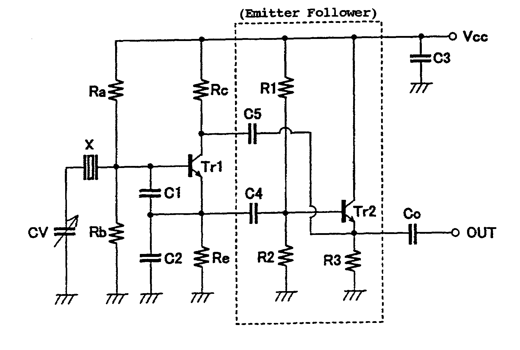
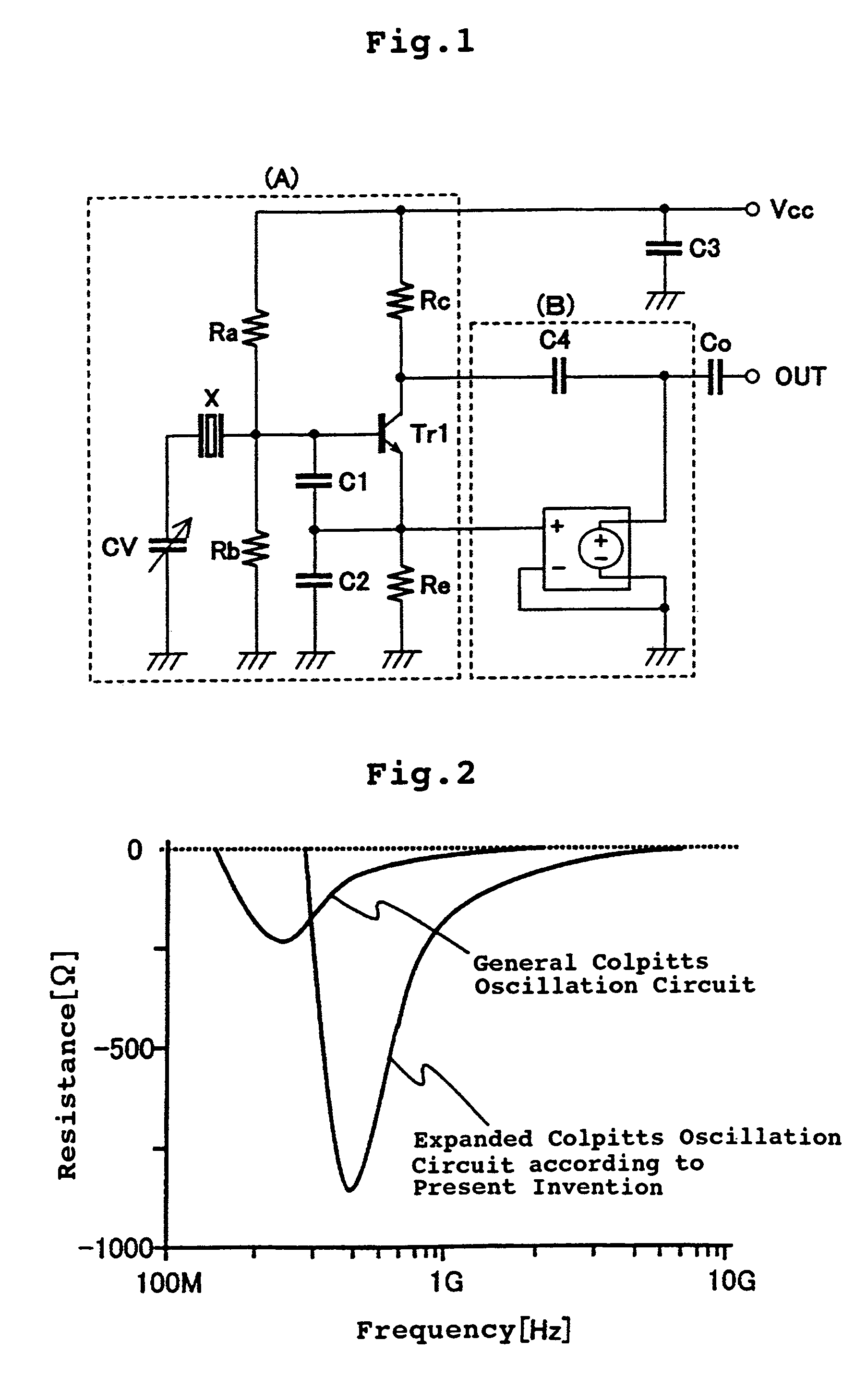
[0022]FIG. 1 is a diagram showing the structure of a Colpitts oscillator according to the present invention (hereinafter called an expanded Colpitts oscillator), and is structured by a Colpitts quartz oscillation circuit using a bipolar transistor within the dashed line indicated by (A), and a voltage source circuit for voltage control (hereinafter referred to as “voltage control circuit”) within the dashed line indicated by (B). The circuit indicated by (A) is the same as the circuit shown in FIG. 9, and the operation thereof has already been described. Therefore, the operation of the circuit indicated by (A) is omitted. An operation of the voltage control circuit indicated by (B) is explained below. The voltage control circuit supplies alternating current without DC component to the collector of Tr1 via a coupling capacitor C4.

[0023]An example of results of simulating the negative resistance characteristic of the expanded Colpitts oscillator according to the present invention is s...


PUM


Abstract

In a Colpitts quartz oscillation circuit, large negative resistance values are obtained in a high frequency band, and in the GHz band in particular. In a piezoelectric oscillator having a Colpitts oscillator, a voltage control circuit, and a coupling capacitor that couples the Colpitts oscillator and the voltage control circuit, an output of the voltage control circuit is feed back to a collector of the Colpitts oscillator via the coupling capacitor.

Description

BACKGROUND OFF THE INVENTION[0001]1. Field of the Invention[0002]The present invention relates to a piezoelectric oscillator, and in particular, to a piezoelectric oscillator which obtains large negative resistances in a high frequency range.[0003]2. Background Art[0004]In recent years, accompanying the developments in wireless communication, there is a demand to make oscillators higher in frequency and more compact. Generally, quartz vibrators have excellent frequency stability, and currently are used over a wide range such as in communication equipment and computers. Usually, Colpitts oscillators, which are structured such that an inductive element is connected between the collector and the base, and a capacitive element is connected between the base and the emitter, and between the collector and the emitter, respectively, are often used as quartz oscillation circuits. FIG. 9 is a basic Colpitts oscillator using a bipolar transistor. As the inductive element between the collector ...

Claims


Application Information

Patent Timeline
Patent Type & Authority Patents(United States)
IPC IPC(8): H03B5/32H03B5/36
CPCH03B5/362
Inventor NOMURA, NORIO
Owner SEIKO EPSON CORP
Why Eureka
Try Eureka