
Composite gas turbine discs for increased performance and reduced cost

a technology of gas turbine discs and composite materials, applied in the direction of machines/engines, climate sustainability, waterborne vessels, etc., can solve the problems of increasing costs, significant technical problems, and difficult production of large industrial gas turbine discs via the conventional cast/wrought processing route, and achieve the effect of reducing alloy costs

Active Publication Date: 2006-09-19
SIEMENS ENERGY INC
View PDF2 Cites 12 Cited by
  • Summary
  • Abstract
  • Description
  • Claims
  • Application Information

AI Technical Summary

Benefits of technology

"The invention provides a new and cost-effective way to make large turbine discs made of mixed materials that offer high performance. The method reduces the use of expensive nickel-based materials and the manufacturing difficulties associated with them. The composite discs have a high nickel rim section and a steel bore section, with a plating, forged welding enhanced agent, or weld filler in between. The discs can be made by forging or welding the rim and bore material together, or by using a welding filler. The high nickel alloy can be a super alloy material, such as having (35% to 60% nickel. The bore section can comprise steel. The method includes steps of forging a ring from a high nickel alloy material, providing a steel ingot, and placing the ring over the ingot. The method can also include plating the ingot with a plating layer before the placing step. In an alternate embodiment, the method includes joining the ring to the ingot with a welding filler material using a process comprising welding."

Problems solved by technology

Although nickel-based alloys are commonly used as the material for aircraft engine discs, application of these materials in industrial gas turbines results in significant technical problems as well as increased costs.
For example, the manufacture of large industrial gas turbine discs via the conventional cast / wrought processing route is difficult.
The starting ingots are already at their size limit for the avoidance of unacceptable segregation related defects, thus limiting the choice of available alloys.
The number of presses with sufficient capacity to forge such discs is also extremely small.
Although the composite discs disclosed by Amos et al. are effective at preventing stress corrosion cracking, the disc composition is not high temperature capable, such as required for use in gas turbine engines and jet engines.

Method used


Image

  • Composite gas turbine discs for increased performance and reduced cost
  • Composite gas turbine discs for increased performance and reduced cost

Examples


Embodiment Construction

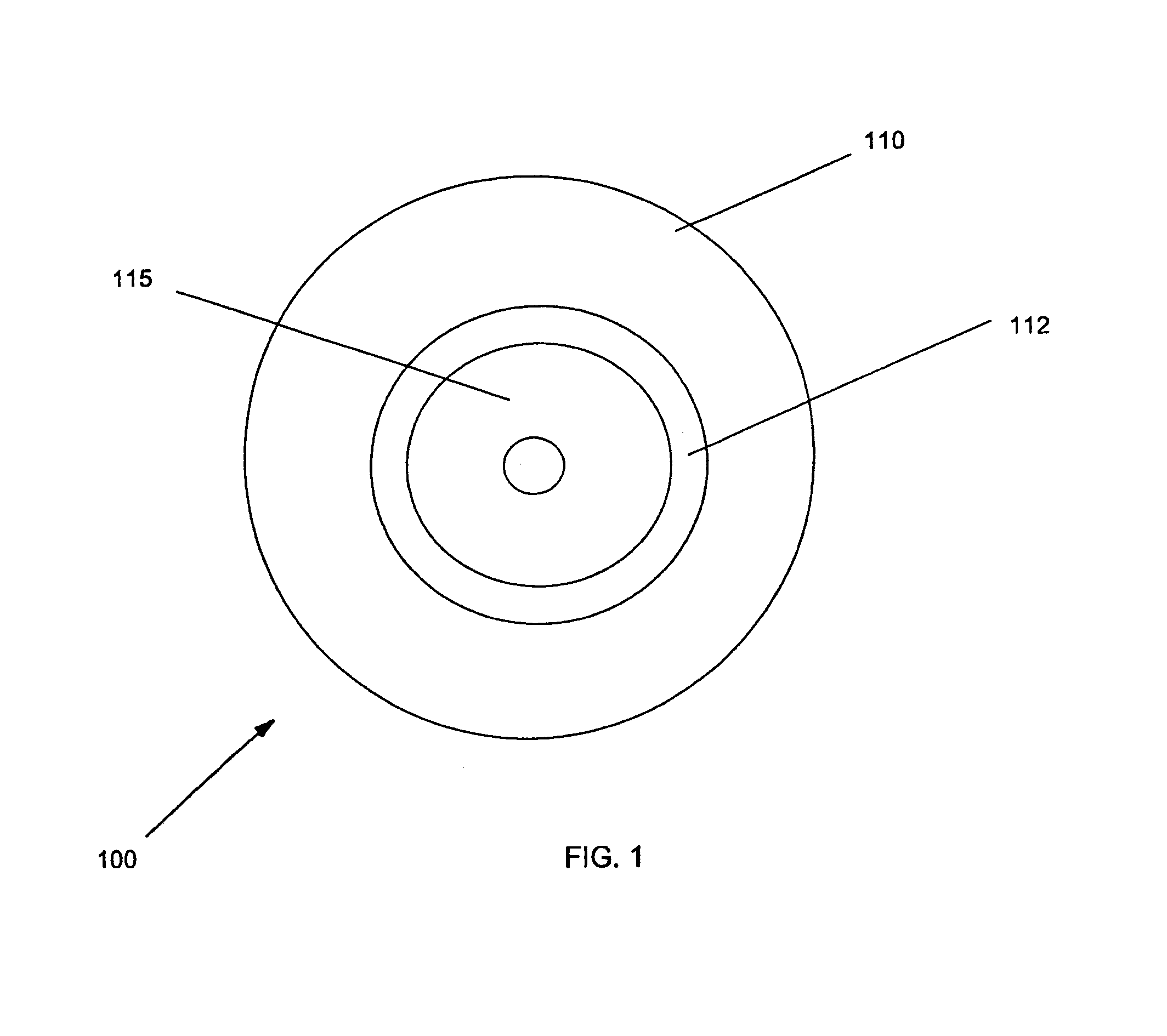
[0016]A composite turbine disc includes a bore section which provides a first melting point, and a rim section comprising a high nickel alloy which provides a higher melting point as compared to the bore section. The invention thus provides composite discs which combine the high strength, toughness, and low cost of low alloy steels in the bore section with the high strength, creep resistance, and oxidation resistance of super alloys in the rim section where high strength, creep resistance, and oxidation resistance are needed for high temperature applications, such as for gas turbines and jet engines. Composite discs according to the invention thus provide significantly increased temperature capability over a comparable system which uses a completely steel disc, at a fraction of the cost of a solid high nickel alloy disc.

[0017]The rim section according to the invention is formed from a high nickel alloy. The high nickel alloy material for the rim is preferably an equiaxed poly-crysta...


PUM

PropertyMeasurementUnit
thickaaaaaaaaaa
thickaaaaaaaaaa
temperatureaaaaaaaaaa

Abstract

A composite turbine disc includes a high nickel rim section and a steel bore section. The rim section is formed from a high nickel alloy which provides a higher melting point as compared to the material used for the bore section. A plating or forged welding enhanced agent layer is disposed between the bore section and rim section. Composite disc can be formed by forging the rim and bore material together, or by welding the rim and bore material together.

Description

FIELD OF THE INVENTION[0001]This invention relates generally to the field of power generation and more specifically to discs for gas turbine engines and jet engines.BACKGROUND OF THE INVENTION[0002]Gas turbine engines include a compressor section for supplying a flow of compressed combustion air, a combustor section for burning a fuel in the compressed combustion air to produce thermal energy, and a turbine section for converting the thermal energy into mechanical energy in the form of a shaft rotation. Many parts of the combustor section and turbine section are exposed directly to hot combustion gasses. For example, the combustor, the transition duct between the combustor and the turbine section, and the turbine stationary vanes, discs and rotating blades are all exposed to hot combustion gases.[0003]It is also known from basic thermodynamics that increasing the firing temperature of the combustion gas may increase the power and efficiency of a combustion turbine. Modern high effic...

Claims


Application Information

Patent Timeline
Patent Type & Authority Patents(United States)
IPC IPC(8): F01D5/02
CPCB23K9/18B23P15/006F01D5/02F01D5/28F01D5/282F05D2300/502B23K2203/08B23K2203/18F05C2201/0466Y02T50/672F05D2230/23F05D2230/232F05D2230/25F05D2300/171F05D2300/603B23K2201/001B23K2101/001B23K2103/04B23K2103/18B23K2103/26Y02T50/60
Inventor SEGLETES, DAVID SCOTTHOELZEL, MICHAEL JOHN
Owner SIEMENS ENERGY INC
Learn More