
Vehicle generator and vehicle generating system

a technology of vehicle generator and generating system, which is applied in the direction of electric generator control, dynamo-electric converter control, electric generator control, etc., can solve the problems of abnormalities that cannot be detected, the battery may be overcharged, and the electric load may be oversupplied

Active Publication Date: 2006-09-12
DENSO CORP
View PDF16 Cites 23 Cited by
  • Summary
  • Abstract
  • Description
  • Claims
  • Application Information

AI Technical Summary

Benefits of technology

The invention provides a reliable vehicle generator that can always operate without the problem of abnormality. The generator includes a voltage regulator, field current sensor, and signal transmitting circuit that can transmit a composite signal representing the detected field current and duty ratio. The system also includes an electronically controlling unit that can control engine power according to the duty ratio or field current, and a warning circuit that can detect abnormality in the field current and duty ratio. The generator temperature measuring circuit can also be included to measure the temperature of the generator. Overall, the invention improves the accuracy and speed of control and ensures the reliable operation of the vehicle generating system.

Problems solved by technology

However, when the demand of electric power sharply changes in such a case that a heavy electric load is connected or disconnected, the battery may be overcharged, or the electric loads may be oversupplied even if a detected amount of the field current is in a normal level.
However, such an abnormality can not be detected until a considerable time has passed.
Even if the abnormality is detected, such a method does not tell whether the abnormality is caused by the field coil or not.

Method used


Image

  • Vehicle generator and vehicle generating system
  • Vehicle generator and vehicle generating system
  • Vehicle generator and vehicle generating system

Examples


Embodiment Construction

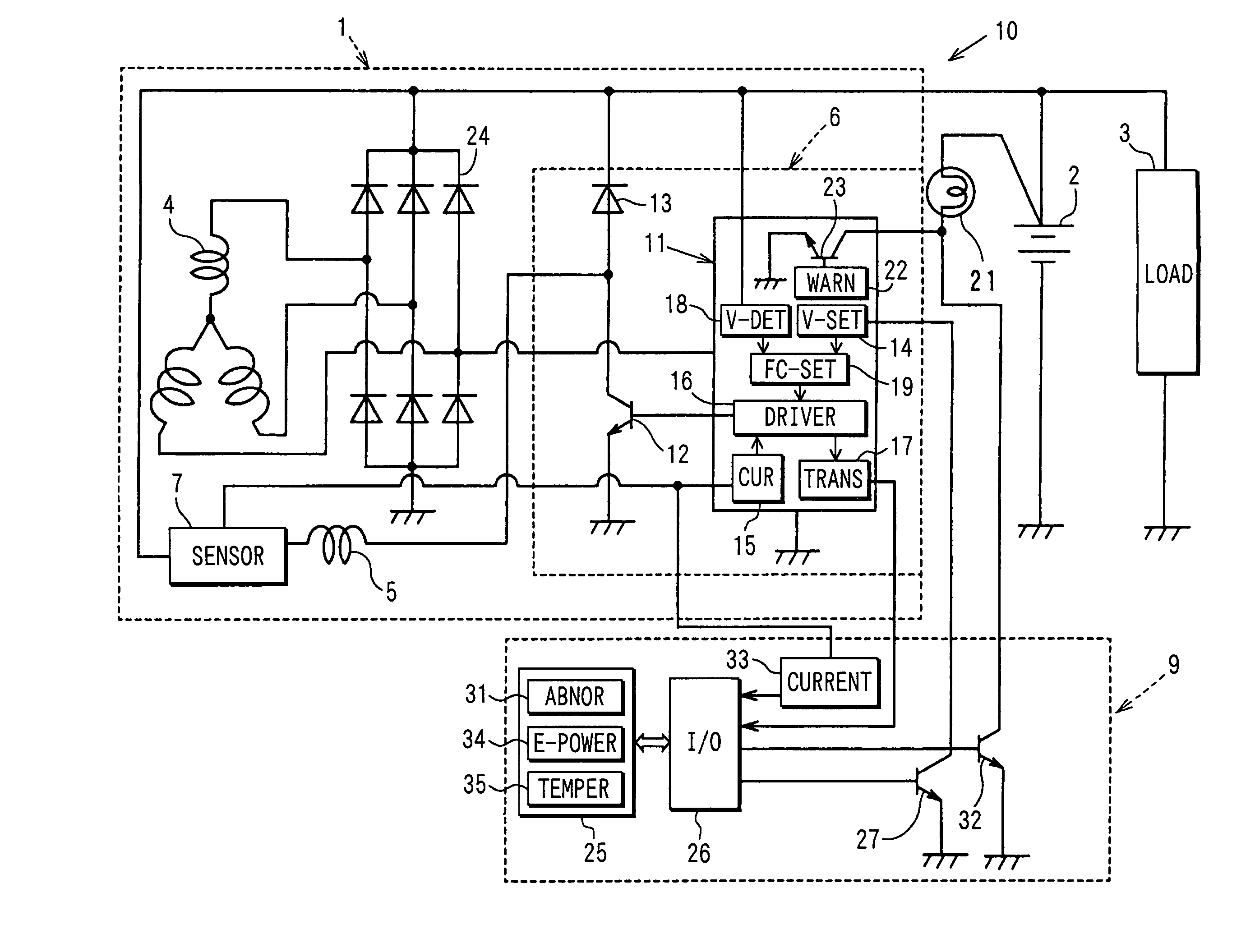
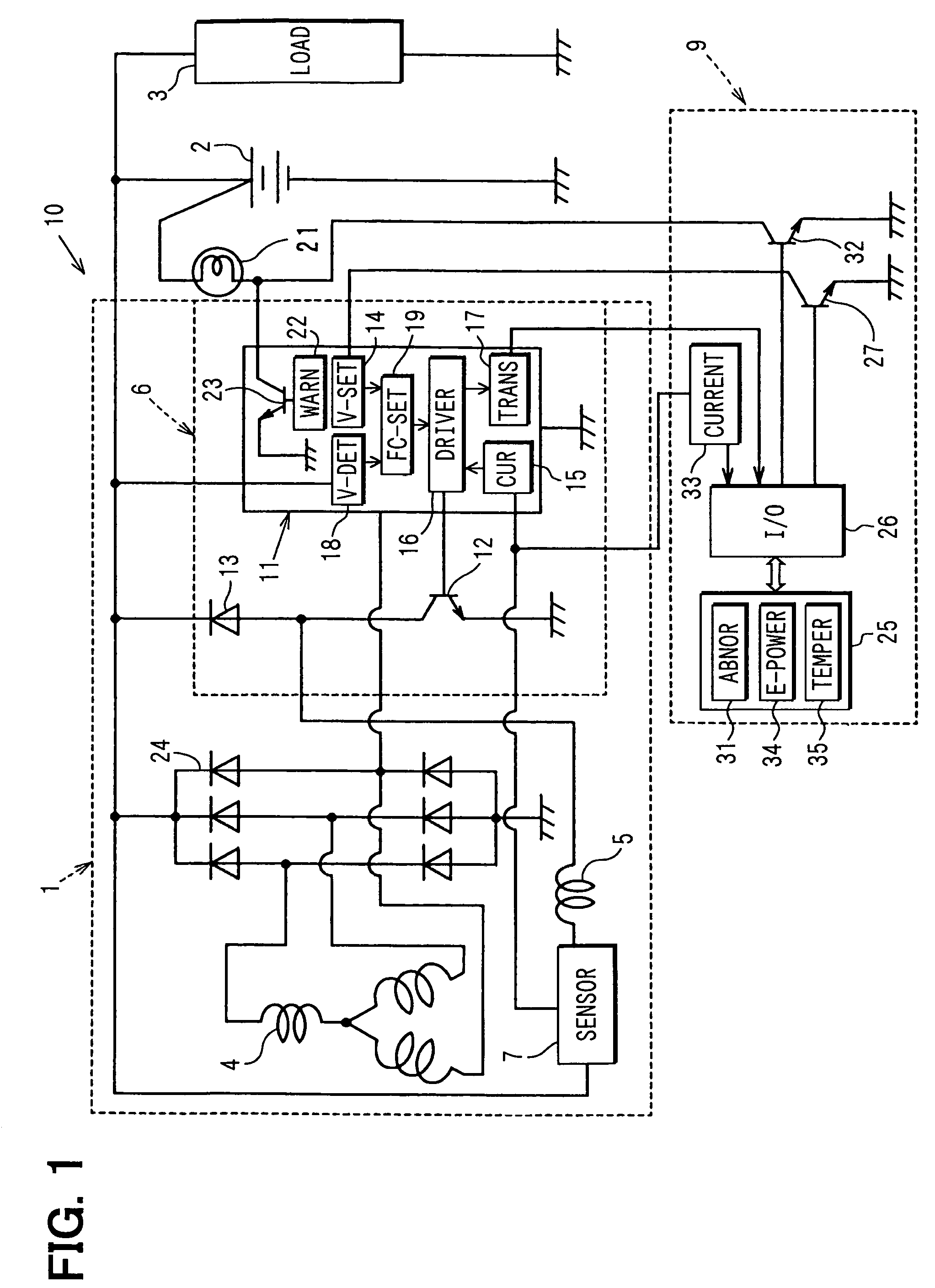
[0023]A vehicle generator 1 according to the first embodiment of the invention, which is mounted in an engine compartment of a vehicle, will be described with reference to FIGS. 1–6.

[0024]As shown in FIG. 1, the vehicle generator 1 according to the first embodiment is connected to a battery 2 and an electric load 3 such as head lamps. The vehicle generator 1 includes an armature coil 4 mounted in a cylindrical stator (not shown) and a cylindrical field coil 5 mounted in a rotor (not shown), a voltage regulator (or an output power control unit) 6, a field current sensor element 7, etc. The vehicle generator 1 forms a generator system 10 together with an electronically control unit (hereinafter referred to ECU) 9.

[0025]The field coil 5 forms a part of the rotor. The rotor includes a Lundell type rotor core and the field coil 5, which is wound around the center of the rotor core. The armature coil 4 includes three phase windings, which generates output power of three-phase-voltage. The...


PUM


Abstract

A vehicle generating system includes a generator for a vehicle, a voltage regulator that supplies field current to the field coil at a variable duty ratio, a field current sensor that detects field current amount, a signal transmitting circuit that transmits a signal representing the detected field current amount and the duty ratio and an electronically controlling unit that receives the signal representing the detected field current amount and the duty ratio and controls the engine according to one of the detected field current amount and the duty ratio.

Description

CROSS REFERENCE TO RELATED APPLICATION[0001]The present application is based on and claims priority from Japanese Patent Application 2004-73888, filed Mar. 16, 2004, the contents of which are incorporated herein by reference.BACKGROUND OF THE INVENTION[0002]1. Field of the Invention[0003]The present invention relates to a vehicle generator and a generating system that includes the vehicle generator.[0004]2. Description of the Related Art[0005]A vehicle generator has been used for charging battery and supplying electric power to various electric loads such as head lamps.[0006]Such a vehicle generator includes an armature coil, a field coil, a voltage regulator, etc.[0007]The voltage regulator usually employs a duty ratio control circuit that controls field current supplied to the field coil through a switch element. For this purpose, a target output power to be supplied to the electric loads and the battery and a target field current are calculated to provide a suitable duty ratio, w...

Claims


Application Information

Patent Timeline
Patent Type & Authority Patents(United States)
IPC IPC(8): H02P9/00F02D29/06F02D41/08H02H7/06H02J7/24H02P9/04H02P11/00
CPCH02P9/006H02J7/245F02D41/083H02J7/2434
Inventor INOKUCHI, TAKATOSHIMAEHARA, FUYUKIASADA, TADATOSHI
Owner DENSO CORP
Learn More