
Method and apparatus of growing a thin film onto a substrate

a technology of thin film and substrate, which is applied in the direction of crystal growth process, chemical vapor deposition coating, coating, etc., can solve the problems of difficult control of thickness and shape of diffusion barrier, risk of microparticle formation already in infeed lines, and general deterioration of thin film quality, so as to reduce reactor design complexity, improve film uniformity, and efficient and simple

Inactive Publication Date: 2006-09-12
ASM INTERNATIONAL
View PDF36 Cites 41 Cited by
  • Summary
  • Abstract
  • Description
  • Claims
  • Application Information

AI Technical Summary

Benefits of technology

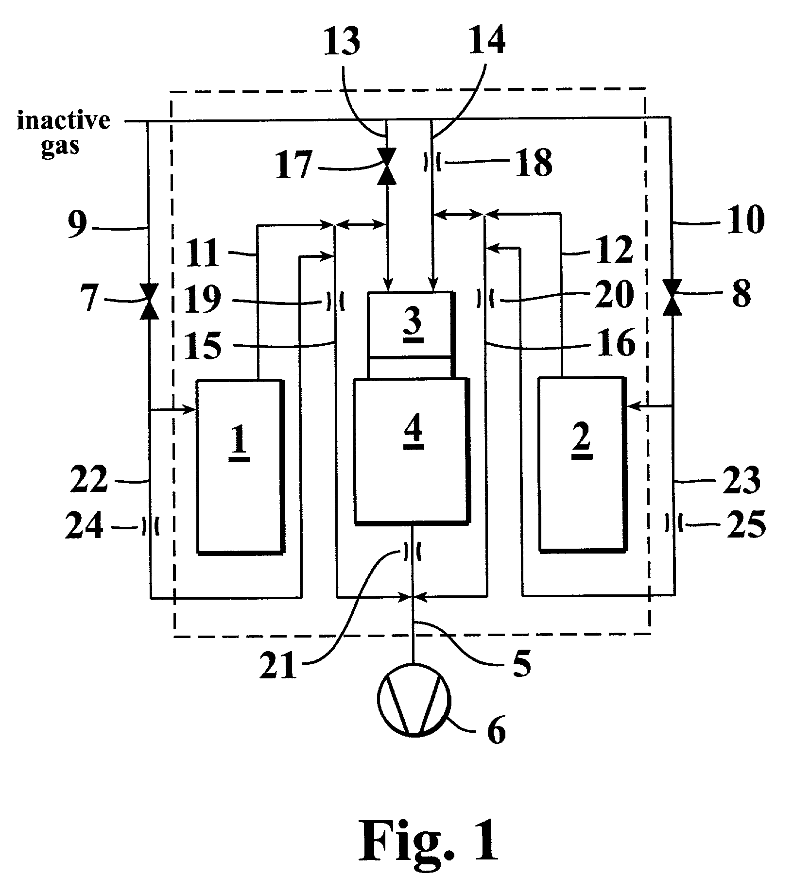
This approach significantly reduces or eliminates the 'tail' of previous reactant pulses, enhancing film uniformity, simplifying reactor design, and reducing design and construction costs, while allowing for shorter purging times between precursor pulses.

Problems solved by technology

Herein arises a risk of microparticle formation already in the infeed lines of the gaseous reactants.
Such microparticles generally have a deteriorating effect on the quality of the deposited thin film.
For instance, the cross sections and shapes of piping in practical reactor constructions vary between, e.g., the inlet manifold and the substrates, whereby the thickness and shape of the diffusion barrier become difficult to control and the starting materials may become carried over into contact with each other.
The diffusion wall may also become destroyed in the nozzles feeding the vapor-phase reactant to the substrates, in gas mixers or at other discontinuity points of the piping.
The laminarity of gas inflow may also become disturbed by a too tight bend in the piping.
Intermixing of starting materials in flow systems cannot be prevented simply by keeping the gas volumes apart from each other, because mixing may also occur due to adherence of molecules from a starting material pulse on the apparatus walls or discontinuities thereof, wherefrom the molecules may then gain access with the molecules of the successive starting material pulse.

Method used


Image

  • Method and apparatus of growing a thin film onto a substrate
  • Method and apparatus of growing a thin film onto a substrate
  • Method and apparatus of growing a thin film onto a substrate

Examples


example

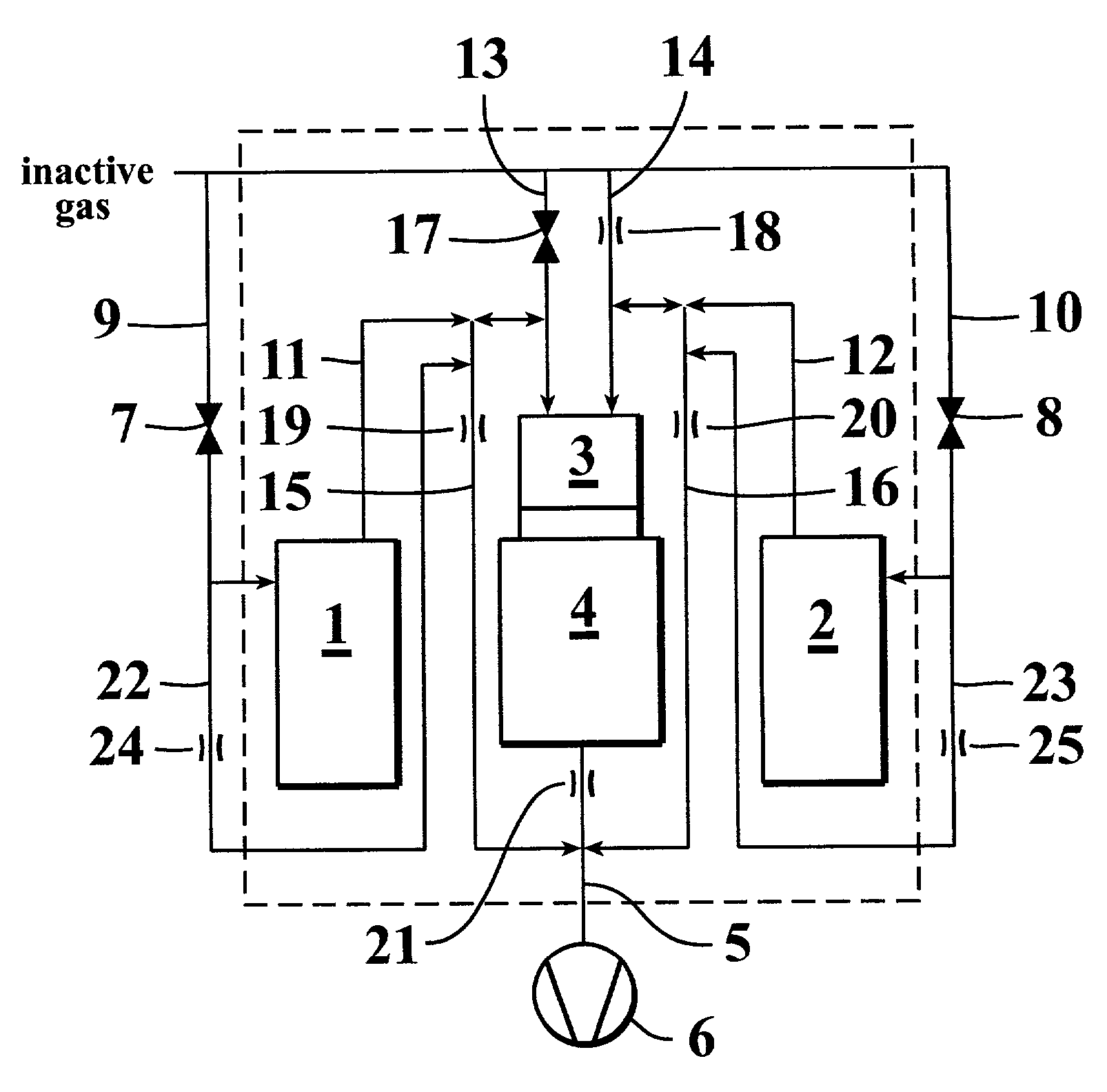
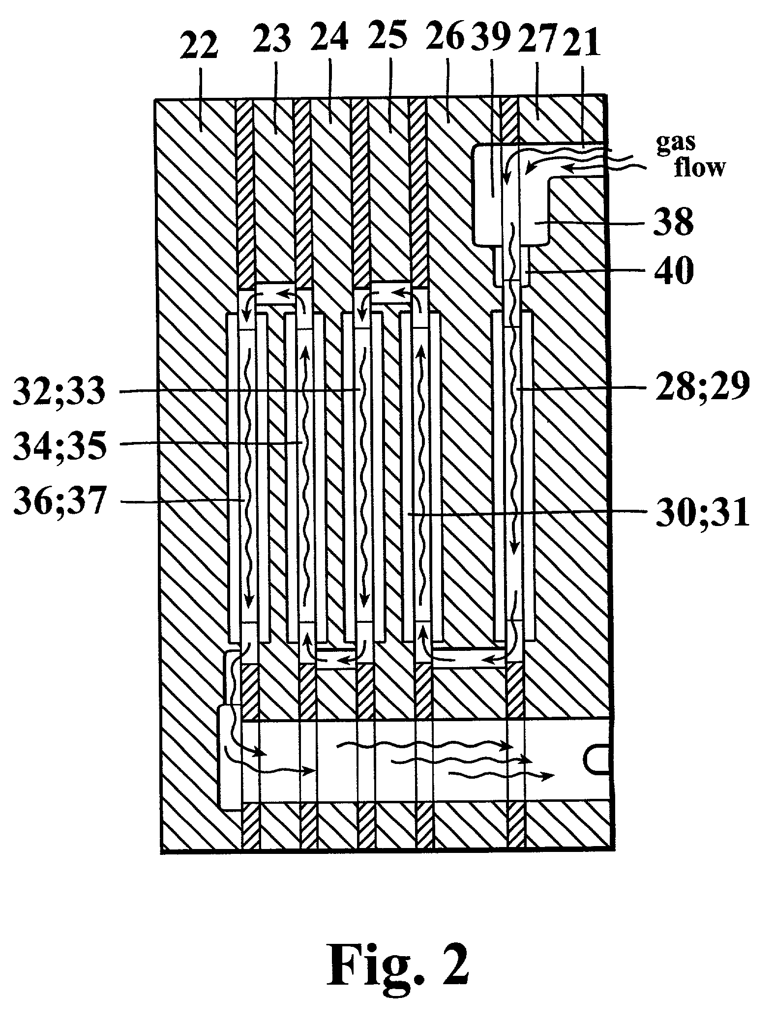
[0058]TiO2 films were grown from TiCl4 and H2O on glass substrates in a reaction space having the structure shown in FIG. 2. The reaction space comprised gas flow channels 21 formed in a reactor block consisting of a plurality of reaction chamber parts or elements 22-27 which were stacked or rather fitted adjacent to each other. The reaction chamber parts can be manufactured from metal or quartz, as in the present case. The glass substrates 28–38 were placed in recesses formed between adjacent reactor parts. In each recess, there were two substrates facing each other, one on each side of a central opening. The substrate pair formed the surfaces which the gas flow was contacted with in the recess and on which a thin film was grown. Five pairs of substrates 28–37 were arranged in a serial arrangement to form a cascade. The reactant pulses were fed into the reaction space from two separate gas flow channels 38, 39. The gas flow of one of the reactants is shown by the arrow-headed line ...


PUM

PropertyMeasurementUnit
pressureaaaaaaaaaa
temperatureaaaaaaaaaa

Abstract

A method and an apparatus for growing a thin film onto a substrate by the ALD process. The apparatus comprises a reaction chamber into which the substrate can be disposed; a plurality of inlet channels communicating with said reaction chamber, said inlet channels being suited for feeding the reactants employed in a thin-film growth process in the form of vapor-phase pulses into said reaction chamber; at least one outlet channel communicating with said reaction chamber, said outlet channel being suited for the outflow of reaction products and excess amounts of reactants from said reaction space; and a pre-reaction chamber arranged immediately upstream of the reaction chamber, said pre-reaction chamber forming a first reaction zone, in which the reactants of successive vapor-phase pulses can be reacted with each other in the vapor phase to form a solid product, whereas said reaction chamber forming a second reaction zone can be operated under conditions conducive to ALD growth of a thin film.

Description

BACKGROUND OF THE INVENTION[0001]1. Field of the Invention[0002]The present invention relates to the production of thin films. In particular, the invention concerns a method of growing a thin film onto a substrate, in which method the substrate is placed in a reaction chamber and it is subjected to surface reactions of a plurality of vapour-phase reactants according to the ALD method to form a thin film. The invention also concerns apparatus for implementing the method.[0003]2. Description of Related Art[0004]Conventionally, thin films are grown out using vacuum evaporation deposition, Molecular Beam Epitaxy (MBE) and other similar vacuum deposition techniques, different variants of Chemical Vapor Deposition (CVD) (including low-pressure and metallo-organic CVD and plasma-enhanced CVD) or, alternatively, the above-mentioned deposition process based on alternate surface reactions, known in the art as the Atomic Layer Deposition, in the following abbreviated ALD, formerly also called ...

Claims


Application Information

Patent Timeline
Patent Type & Authority Patents(United States)
IPC IPC(8): C30B25/00C30B25/08C23C16/44C23C16/40C23C16/455C30B25/02C30B25/14H01L21/205
CPCC23C16/405C23C16/45502C23C16/45527C30B25/14C30B25/02C30B25/08C23C16/45546
Inventor LINDFORS, SVEN
Owner ASM INTERNATIONAL
Learn More