
Engine crankcase structure

a crankcase and engine technology, applied in the direction of lubricant mounting/connection, lubrication elements, pressure lubrication, etc., can solve the problems of many limitations of the balancer layout, and achieve the effect of reducing the loss of friction

Active Publication Date: 2006-09-12
HONDA MOTOR CO LTD
View PDF7 Cites 22 Cited by
  • Summary
  • Abstract
  • Description
  • Claims
  • Application Information

AI Technical Summary

Benefits of technology

This configuration lowers the engine's center of gravity, miniaturizes the engine, enhances layout flexibility, reduces manufacturing complexity and costs, and improves fuel efficiency by minimizing friction loss and oil consumption, while maintaining the balancer's effectiveness in reducing engine vibration.

Problems solved by technology

Accordingly, there are many limitations on the balancer layout.

Method used


Image

  • Engine crankcase structure
  • Engine crankcase structure
  • Engine crankcase structure

Examples


Embodiment Construction

[0025]An embodiment of the present invention will now be described with reference to the accompanying drawings.

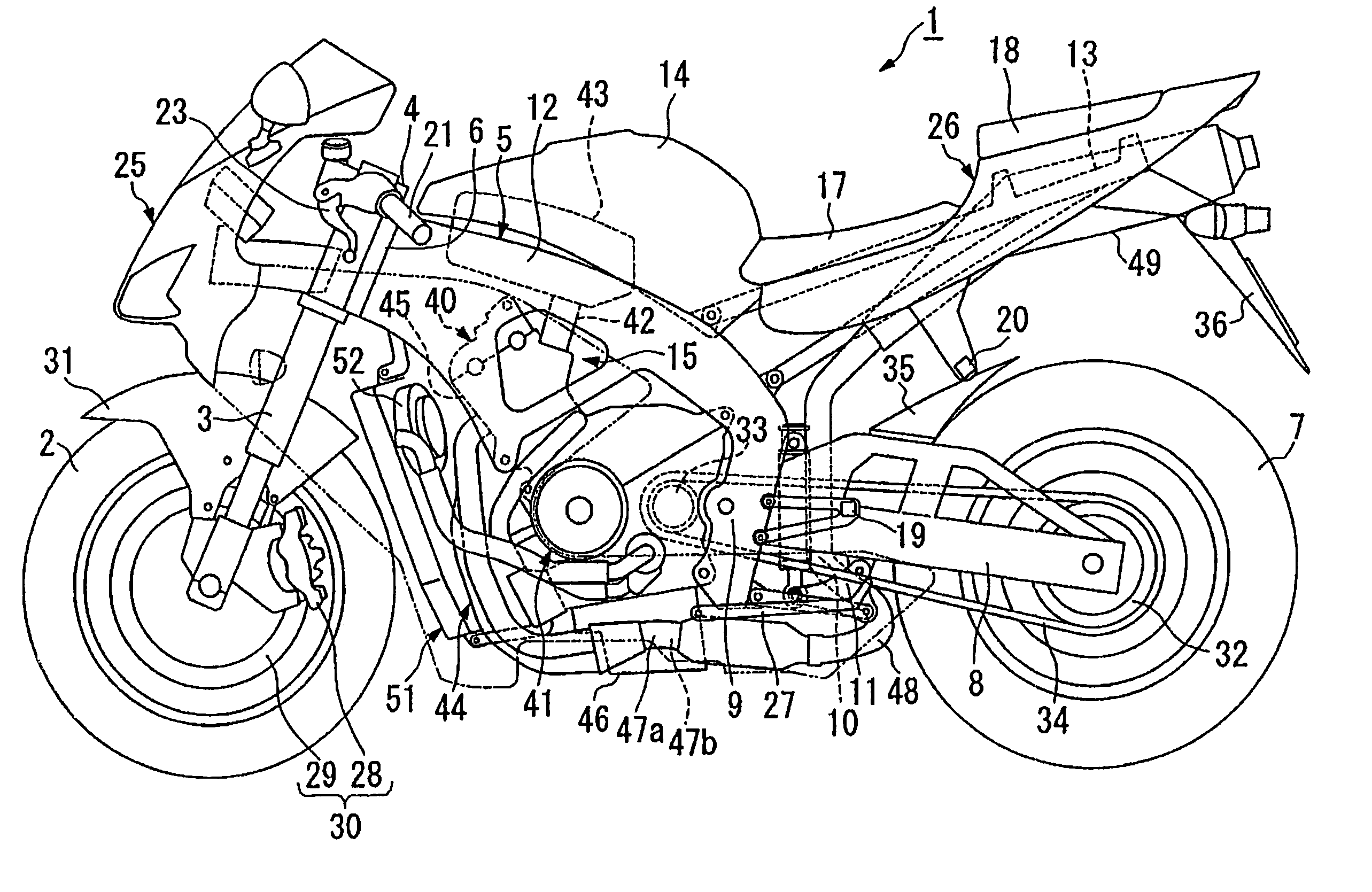
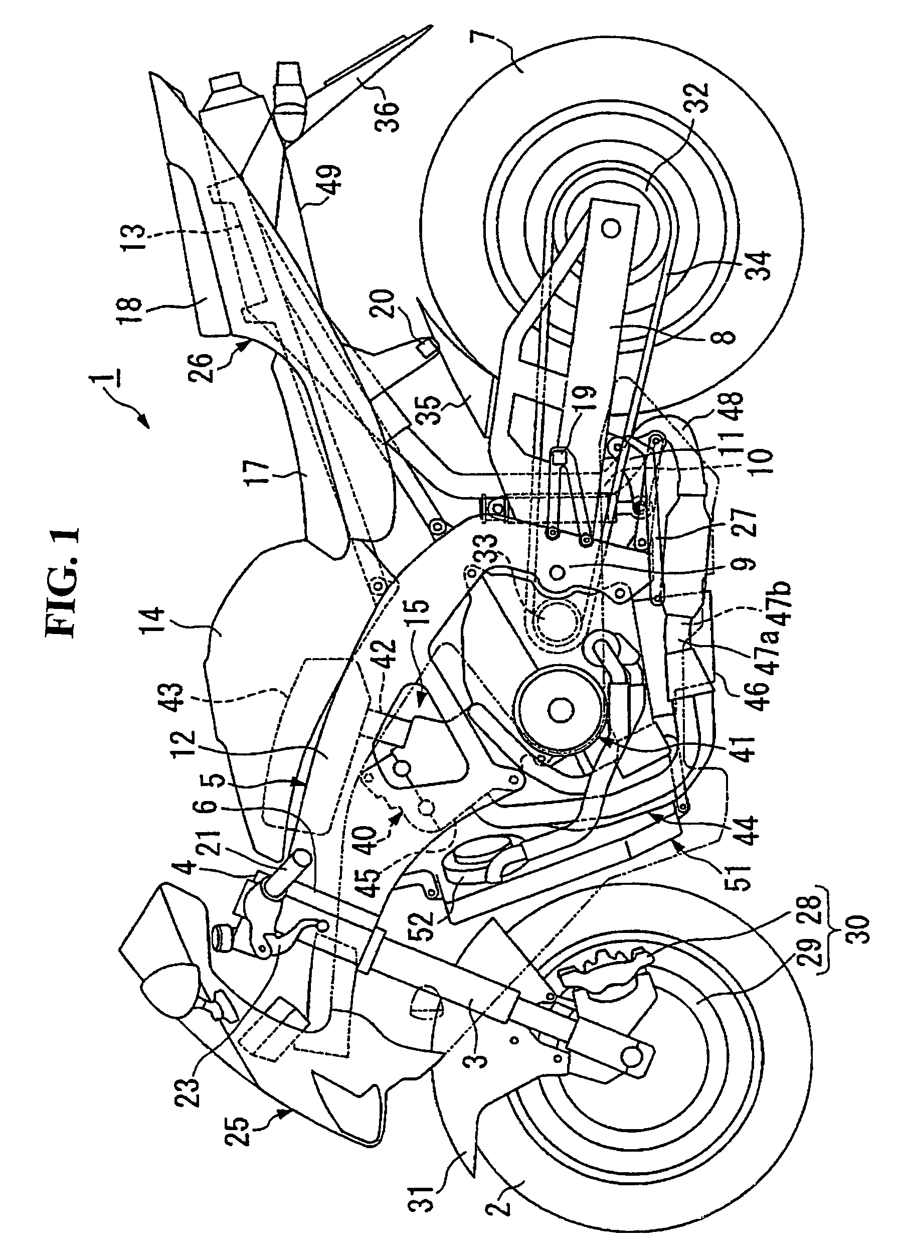
[0026]As shown in FIG. 1, a front fork 3 that supports a front wheel 2 of a motorcycle 1 is supported by a head pipe 6 provided on the front end of a body frame 5 via a steering stem 4 so that the front fork can be steered. A rear fork 8 that supports a rear wheel 7 is supported by a pivot part 9 provided on an intermediate part of the body frame 5 and the body of an engine 15 so that the rear fork can be vertically moved. The upper end of a rear cushion 10 is attached in the vicinity of the pivot part of the rear fork 8. The lower end of the rear cushion 10 is attached to a lower part of the pivot part 9 and a lower part of the body of the engine 15 via a link mechanism 11.

[0027]A main frame 12 of the body frame 5 extends backward and downward from an upper side of the head pipe 6 on the right side and on the left side. A rear end is curved downward and ranges to the pivot...


PUM


Abstract

To miniaturize an engine, to concentrate heavy masses and to reduce friction loss of a balancer. An engine crankcase structure in which a crankcase is vertically partitioned into an upper case and a lower case, each journal supporter is formed in the upper case and in the lower case so that the rotational axis of a crankshaft is located on a partition face of the crankcase in parallel with a direction of the width of the body. The crankshaft is supported so that the crankshaft can be rotated. An oil filter is directly attached to the lower case. An oil cooler and a secondary balancer are arranged in the front of the lower case.

Description

CROSS-REFERENCE TO RELATED APPLICATIONS[0001]This nonprovisional application claims priority under 35 U.S.C. § 119(a) on Patent Application Ser. No. 2003-277865, filed in Japan on Jul. 22, 2003, the entirety of which is incorporated herein by reference.BACKGROUND OF THE INVENTION[0002]1. Field of the Invention[0003]The present invention relates to the crankcase structure of an engine. In particular, the present invention relates to the crankcase structure of an engine provided with a balancer.[0004]2. Description of Background Art[0005]In the background art, some engines mounted in a vehicle such as a motorcycle are provided with a secondary balancer. The secondary balancer is provided with a balancer shaft parallel to the crankshaft and is configured so that secondary engine vibration is effectively reduced by rotating the secondary balancer by two times the number of revolutions of the crankshaft (see JP-A-2000-310286). A balancer according to the above background art is configure...

Claims


Application Information

Patent Timeline
Patent Type & Authority Patents(United States)
IPC IPC(8): F02B75/06F02B67/00F01M5/00F01M11/03F02B61/02F02B77/00F02F7/00
CPCF02B61/02F01M11/02
Inventor KAWAKUBO, HIROYUKIGUNJI, TORU
Owner HONDA MOTOR CO LTD
Learn More