
Method for providing a backing member for an acoustic transducer array

Inactive Publication Date: 2006-09-12
VERMON
View PDF5 Cites 20 Cited by
  • Summary
  • Abstract
  • Description
  • Claims
  • Application Information

AI Technical Summary

Benefits of technology

[0012]In accordance with a first aspect of the invention, an improved method is provided for making matrix array transducers (as well as other transducers, as described below). This aspect of the invention is particularly concerned with making the backing block or layer of each trans

Problems solved by technology

However, these manufacturing methods have led to compromises in performance and to complexity in fabrication.
The use of this technique for a matrix array is not practical because the number of elements involved is significantly higher.
Standard flexible circuits do not have the density required for this number of elements and thicker multilayer printed circuit boards, such as disclosed in the U.S. Pat. No. 5,855,049 (Corbett et al) degrade the performance of the transducer when placed between the piezoelectric material and the backing material.
These prior art attempts sometimes include the use of so-called “visible” multi-layer circuits which dramatically degrade the transducer response from reflections and sometimes use a connecting method so complicated that the resulting transducer is simply too expensive and unreliable to manufacture.
This method however requires complicated tooling and methods to align the individual conductors.
Furthermore the conductors are so thin as to make it difficult to achieve a reliable contact, and the conductors can collapse if excessive force is exerted on the backing.

Method used


Image

  • Method for providing a backing member for an acoustic transducer array
  • Method for providing a backing member for an acoustic transducer array
  • Method for providing a backing member for an acoustic transducer array

Examples


Embodiment Construction

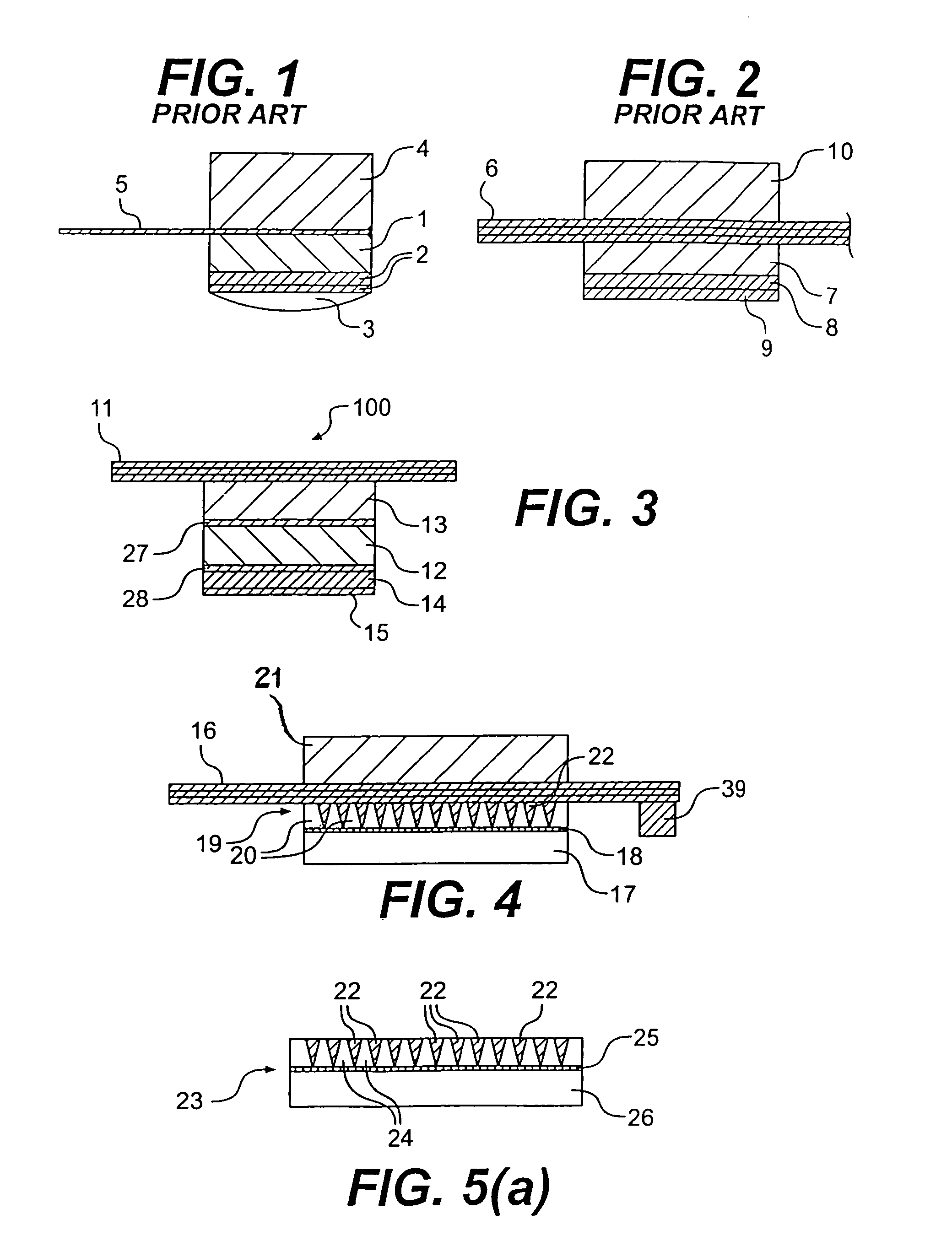
[0036]Considering the components of the matrix array transducer of the invention beginning with the piezoelectric elements, and referring to FIG. 3, a matrix array 100 is shown which includes a piezoelectric member 12 sandwiched between a ground electrode 28 and a negative polarization electrode 27. Piezoelectric member 12 is ground on both faces to have a constant thickness that is given by the following equation: t=v / (2 * Fa), where t is the thickness, v is the velocity of sound in the material, and Fa is the anti-resonance frequency. The surfaces of member 12 are then electro-plated with copper or gold. For negative impulse excitation systems, the positive polarization orientation is marked as the ground electrode 28 of the transducer array 100. A dicing operation is performed on the rear, negative polarization electrode 27. This operation involves separating the rear electrode 27 into a plurality of individual elements that correspond to the elements of the transducer. It is imp...


PUM

PropertyMeasurementUnit
Electrical conductoraaaaaaaaaa
Areaaaaaaaaaaa
Water absorptionaaaaaaaaaa

Abstract

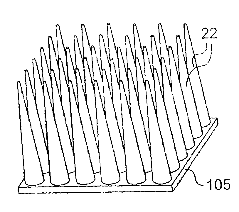
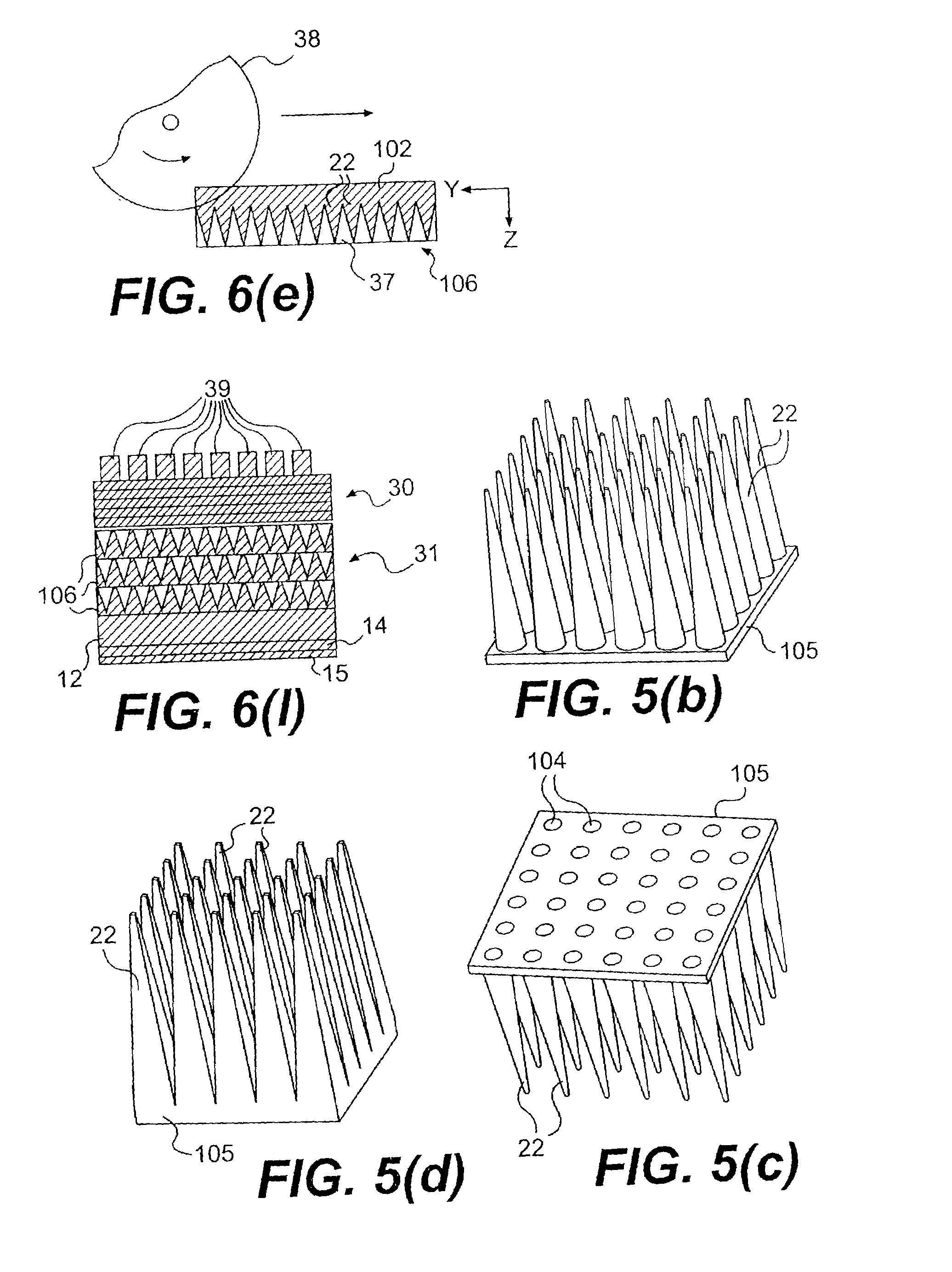
A method is provided for making a backing layer for an ultrasonic matrix array transducer useful in medical imaging and the like. A conductive grid is provided which includes a plurality of micro-contacts each joined together by a common base so that spaces are provided between the free ends of the contacts. A mold for the grid is filled with an acoustically absorbent material such that the absorbent material fills the spaces between the contacts, so as to produce a block when cured. The common base is removed so as to separate the contacts from one another within the block. Further machining exposes the opposite ends of micro-contacts so that a like number of contact faces or pads are provided at opposed surfaces of the backing layer. Improved transducer constructions are also disclosed.

Description

CROSS-REFERENCE TO RELATED APPLICATIONS[0001]This application is a division of application Ser. No. 09 / 577,342, filed on May 24, 2000.BACKGROUND OF THE INVENTION[0002]1. Field of the Invention[0003]The present invention relates to ultrasonic transducers such as used for diagnostic imaging, non-destructive material testing and treatment of human organs and to methods for making such transducers.[0004]2. Background of the Invention[0005]Many types of transducers have been developed for a variety of imaging applications. Ultrasonic devices such as single element, annular arrays, one-dimensional arrays, 1.5 dimensional linear arrays and two-dimensional (2D) matrix arrays are examples of devices used as medical transducers. Recently, matrix shaped ultrasonic transducers designed for three-dimensional (3D) imaging capabilities have been introduced into the marketplace. Reference is made, for example, to U.S. Pat. No. 5,732,706 (White et al) which discloses a piezoelectric matrix array tra...

Claims


Application Information

Patent Timeline
IPC IPC(8): H04R31/00G10K11/00
CPCG10K11/002Y10T29/42Y10T29/49169Y10T29/49176Y10T29/49147Y10T29/4913Y10T29/49172Y10T29/49126Y10T29/49158Y10T29/49155Y10T29/4902Y10T29/49002Y10T29/49005Y10T29/4908Y10T83/0457Y10T83/2079Y10T83/0538
Inventor AIME, FLESCH
Owner VERMON
Learn More