
High voltage level converter using low voltage devices

a technology of low voltage and voltage level converter, which is applied in the direction of differential amplifier, pulse automatic control, generating/distributing signals, etc., can solve the problems of poor reliability and performance of voltage level converter, the voltage level converter with thick oxide transistor cannot withstand very low operating voltage, and the voltage level converter with thick oxide transistor is not efficient or reliable at low voltag

Active Publication Date: 2006-09-05
NORTH STAR INNOVATIONS
View PDF15 Cites 28 Cited by
  • Summary
  • Abstract
  • Description
  • Claims
  • Application Information

AI Technical Summary

Benefits of technology

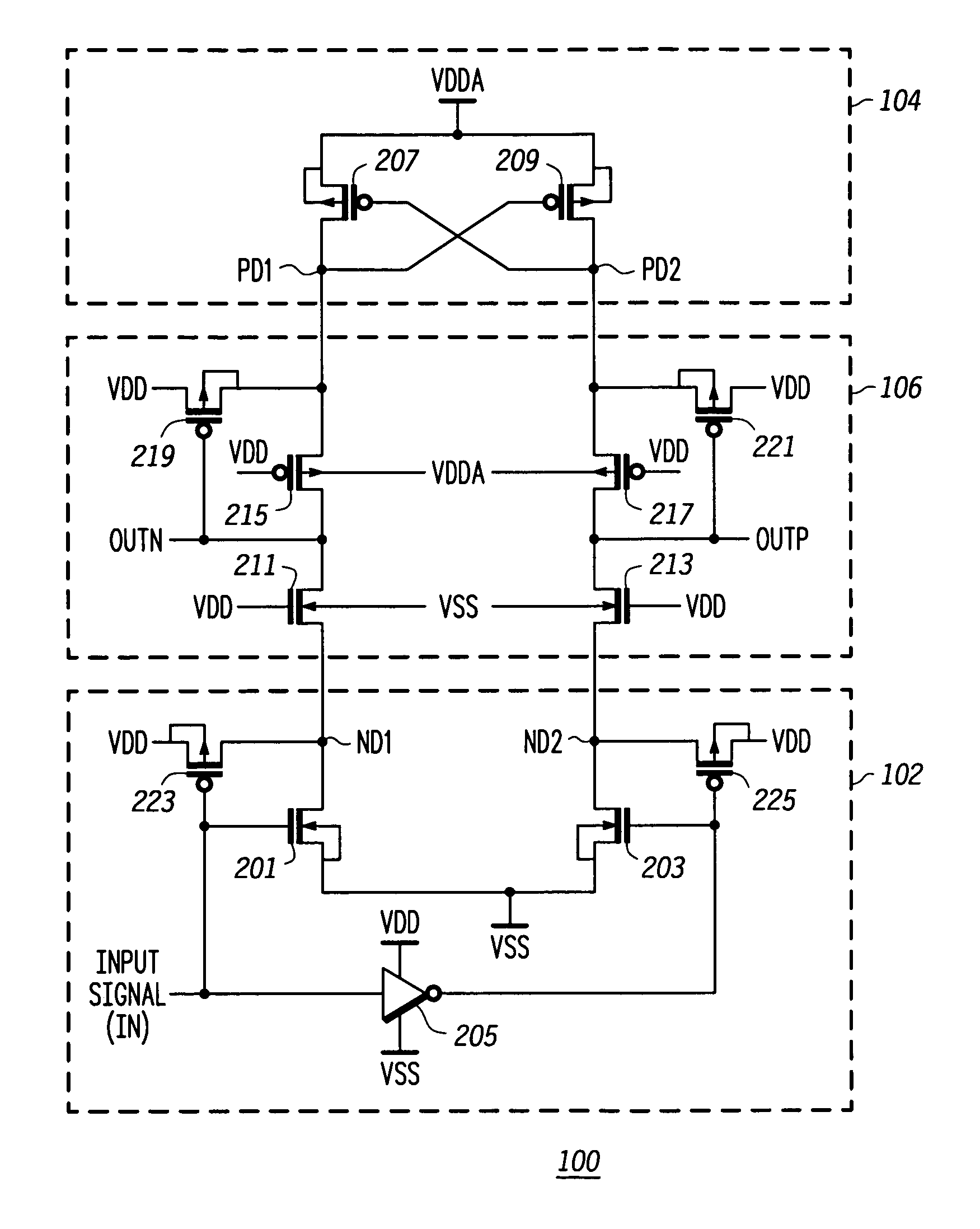
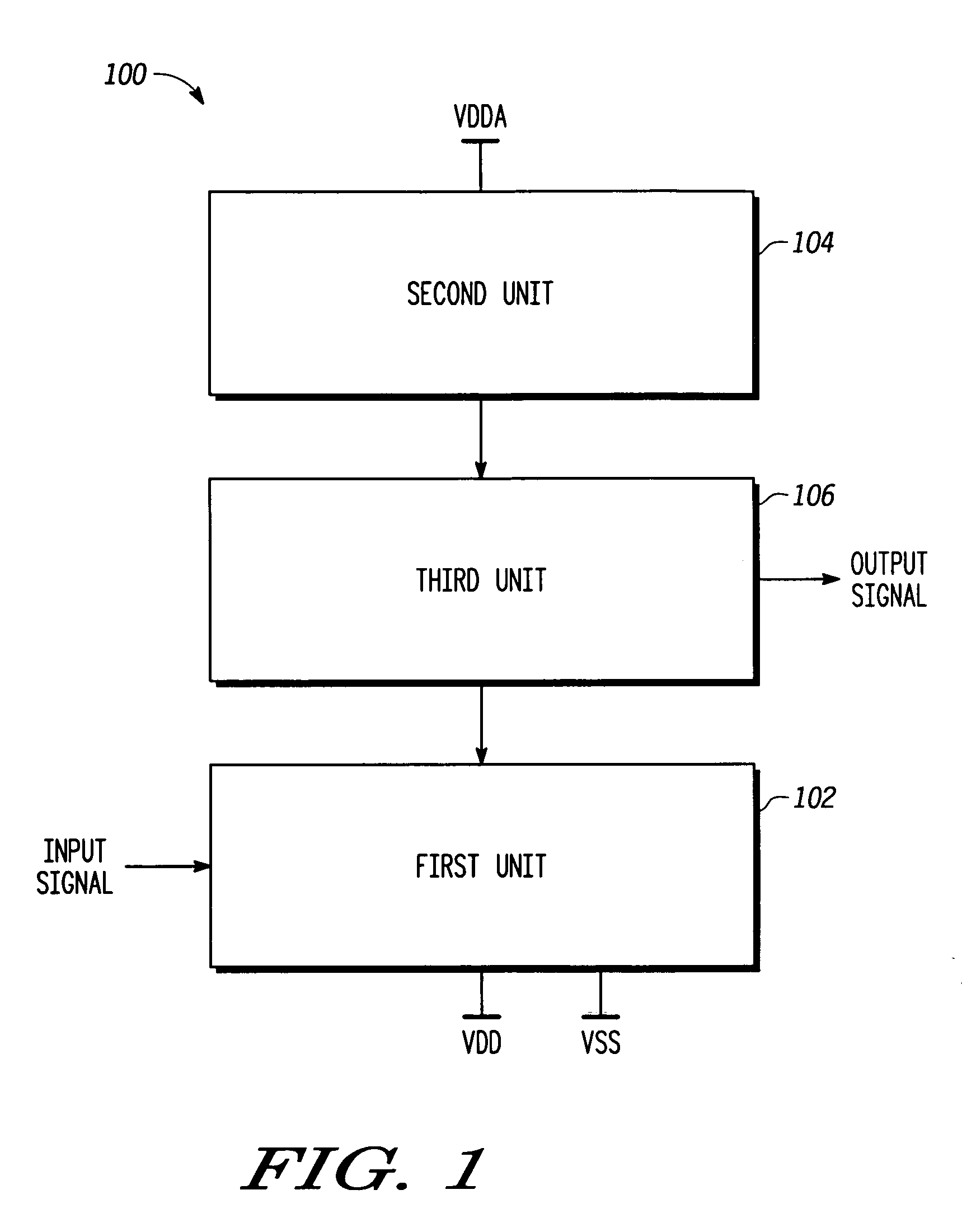
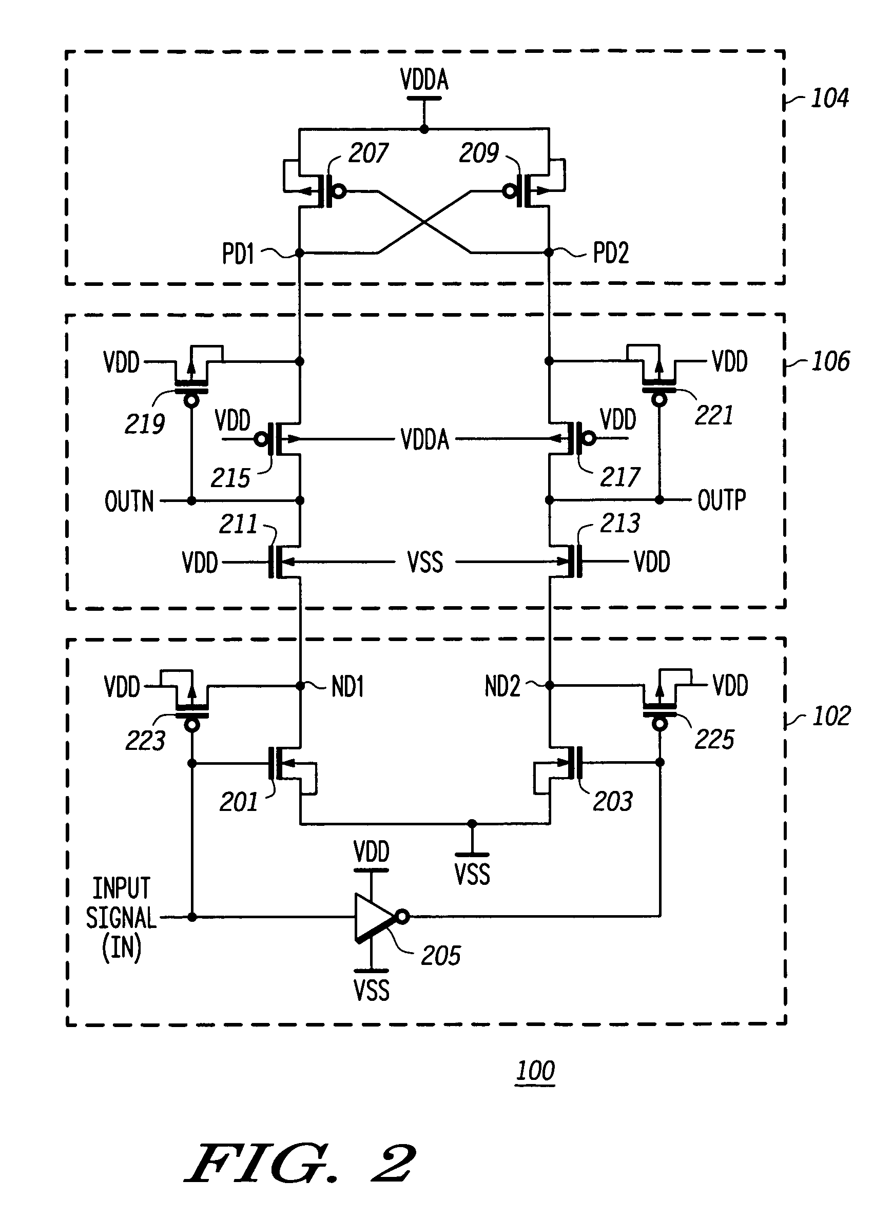
"The present invention provides a voltage level converting circuit that can efficiently and reliably convert signals between different voltage levels. The circuit uses thin oxide transistors, which allows for faster switching and lower operating voltages. The circuit includes a first unit, a second unit, and a third unit that couple the first and second units. The first unit operates at a first power supply voltage and includes a first NMOS transistor and a second NMOS transistor, while the second unit operates at a second power supply voltage and includes a first PMOS transistor and a second PMOS transistor. The third unit includes a third NMOS transistor, a third PMOS transistor, a fifth PMOS transistor, and a sixth PMOS transistor. The circuit can be cost-effective and reliable at low voltages."

Problems solved by technology

Thick oxide transistors cannot withstand very low operating voltages.
Since the operating and threshold voltages are close, the reliability and performance of the voltage level converter is adversely affected.
Consequently, voltage level converters with thick oxide transistors are not efficient or reliable at low voltages and limit the frequency of operation as well.
Also, manufacturing thick oxide transistors requires extra masks and hence, more steps are required in the fabrication process, which leads to an increase in the cost of manufacture.

Method used


Image

  • High voltage level converter using low voltage devices
  • High voltage level converter using low voltage devices
  • High voltage level converter using low voltage devices

Examples


Embodiment Construction

[0012]The detailed description set forth below in connection with the appended drawings is intended as a description of the presently preferred embodiments of the invention, and is not intended to represent the only form in which the present invention may be practiced. It is to be understood that the same or equivalent functions may be accomplished by different embodiments that are intended to be encompassed within the spirit and scope of the invention.

[0013]For the sake of convenience, the terms that have been used to describe the various embodiments are defined below. It is to be noted that these definitions are provided merely to aid the understanding of the description, and are in no way to be construed as limiting the scope of the invention.

[0014]The term “voltage level” refers to the voltage corresponding to the logic values of a signal. For example, a signal at logic low may have a voltage of about 0.0V, while a signal at logic high may have a voltage of about 1.2V.

[0015]The ...


PUM


Abstract

A circuit for converting an input signal at a first voltage level to an output signal at a second voltage level uses only thin oxide transistors. The circuit includes a first unit operating at a first power supply voltage and receiving the input signal, a second unit operating at a second power supply voltage, and a third unit coupling the first unit to the second unit. The third unit enables generation of the output signal. Use of an extra fabrication mask for thick oxide transistors is avoided by using only thin oxide transistors.

Description

BACKGROUND OF THE INVENTION[0001]The present invention relates generally to integrated circuits, and more particularly to voltage level converting circuits for shifting digital signals between two different voltage levels.[0002]With recent technological developments, integrated circuits (IC) with very low operating voltages are being used more often. In a circuit that has two ICs operating at different internal operating voltages, a voltage level converter is used to facilitate the transfer of signals between the two ICs. For example, if the first IC, operating at 1.2V, is used in conjunction with the second IC, operating at 2.5V, a voltage level converter is incorporated in the second IC. The voltage level converter translates the output signal of the first IC from the operating voltage level of 1.2V to an input voltage of 2.5V for the second IC.[0003]Voltage level converter circuits are typically made using a plurality of Metal-Oxide-Semiconductor Field Effect Transistors (MOSFET)...

Claims


Application Information

Patent Timeline
Patent Type & Authority Patents(United States)
IPC IPC(8): H03L5/00G06F1/04H03F3/45
CPCH03F3/45183
Inventor KHAN, QADEER A.TRIPATHI, DIVYAMISRI, KULBHUSHAN
Owner NORTH STAR INNOVATIONS
Learn More