
Apparatus for extruding ceramic molding

a technology for extruding apparatus and ceramic molding, which is applied in the direction of auxillary shaping apparatus, ceramic extrusion dies, butter manufacture, etc., can solve the problems of large ratio of outer diameter to screw diameter, difficult to manufacture ceramic moldings with large diameters using small extruding apparatus, etc., and achieve high quality and enhanced uniformity

Inactive Publication Date: 2006-09-05
DENSO CORP
View PDF25 Cites 20 Cited by
  • Summary
  • Abstract
  • Description
  • Claims
  • Application Information

AI Technical Summary

Benefits of technology

The present invention provides an extruding apparatus for ceramic moldings that can be extruded through a small extrusion screw. The apparatus includes a pressure screw part and a diffusion screw part, with the diffusion screw part having a larger diameter than the pressure screw part. The extrusion screw has a pressure screw part with a single thread or multiple threads, and a diffusion screw part with a single thread or multiple threads. The extrusion screw is designed to pressurize the ceramic material and supply it to the molding die. The apparatus can produce high-quality ceramic moldings with large diameters. The small extruding apparatus is designed to solve the problem of large ceramic moldings being unable to be extruded through traditional extrusion screws.

Problems solved by technology

However, the above conventional screw type extruding apparatus has the following problems.
It is difficult to extrude the ceramic molding of which the ratio of the outer diameter thereof to the screw diameter exceeds a predetermined value.
This is the reason that it is difficult to manufacture a ceramic molding having a large diameter using a small extruding apparatus.

Method used


Image

  • Apparatus for extruding ceramic molding
  • Apparatus for extruding ceramic molding
  • Apparatus for extruding ceramic molding

Examples


embodiment 1

[0078 will be explained first. The extruding apparatus according to the embodiments of the present invention will be explained with reference to FIGS. 1–3.

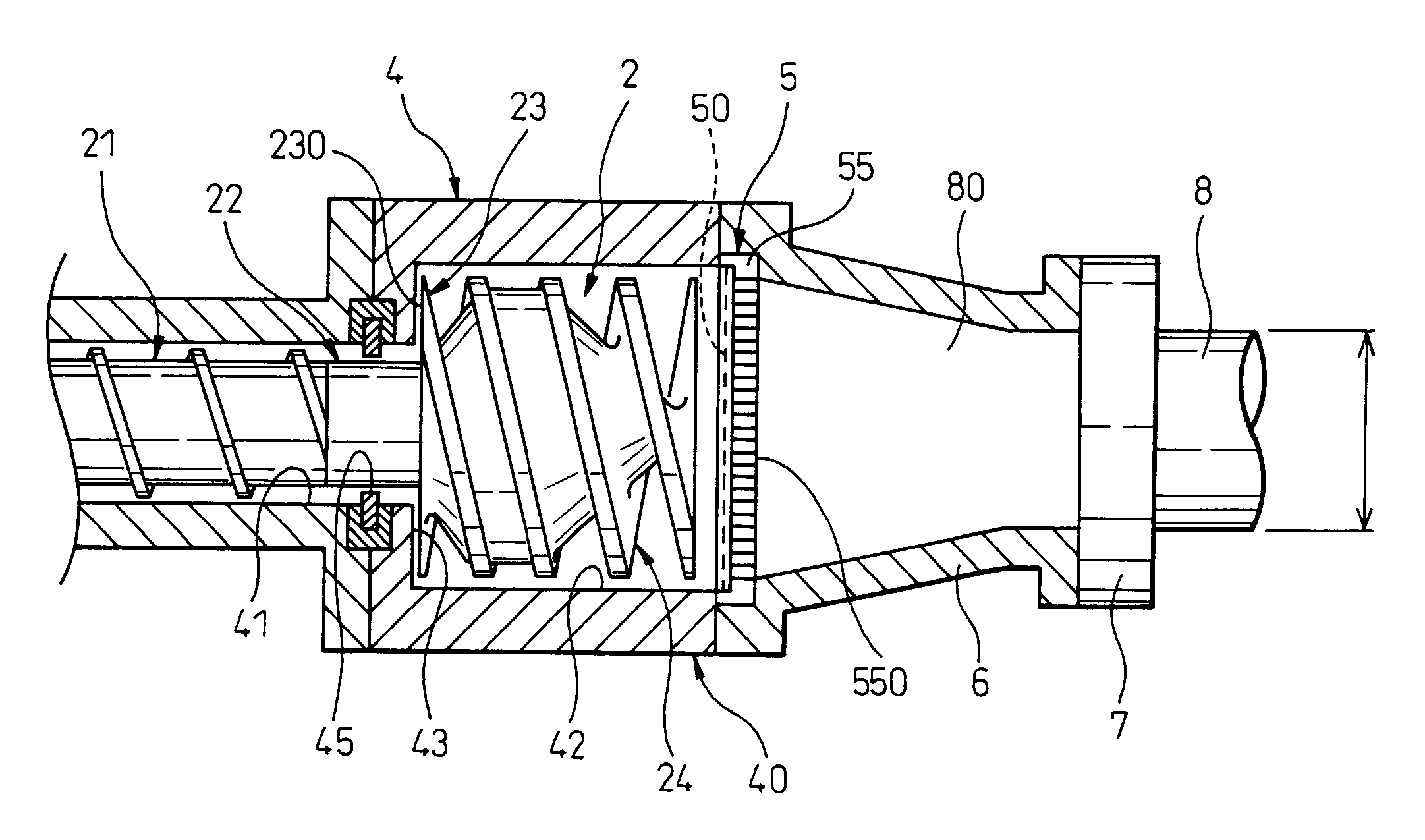
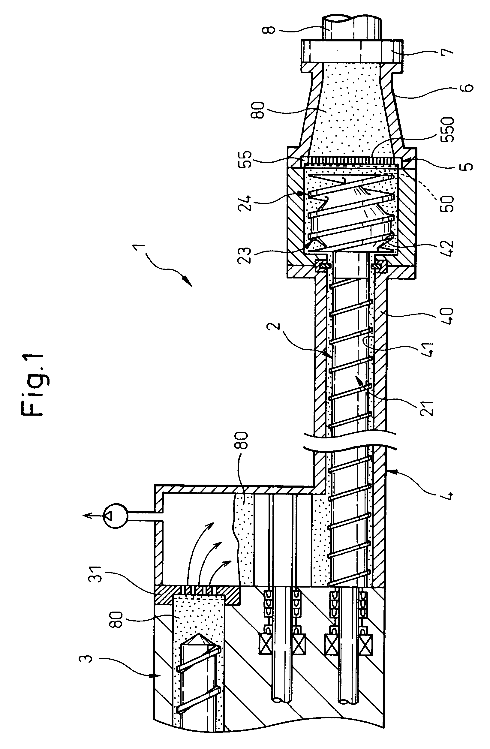
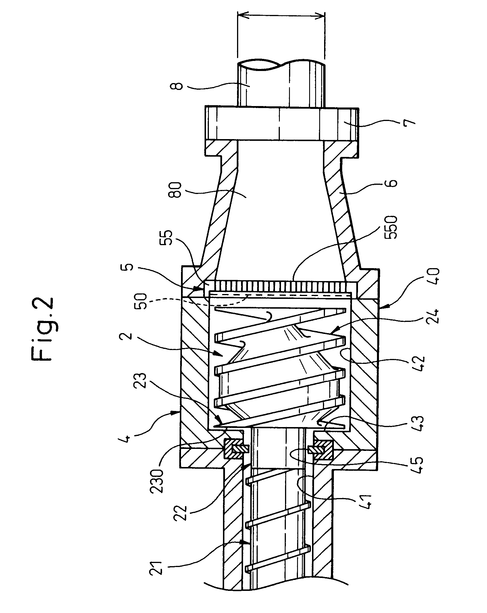
[0079]As shown in FIG. 1, the extruding apparatus 1 of the present embodiment has the molding die 7 for forming the ceramic molding 8 and the screw extruder 4 containing the extrusion screw 2 to knead and guide the ceramic material 80 toward the molding die 7.

[0080]The extrusion screw 2 is provided with the pressure screw part 21 and, at its front end, with the diffusion screw part 24.

[0081]As shown in FIG. 3, the pressure screw part 21 is provided with a first lead 215 of a single thread or more than one thread in the form of a spiral ridge, on an outer peripheral surface of the first shaft body 211.

[0082]The diffusion screw part 24 is located coaxially to the first shaft body 211 and is provided with the second lead 245 of two threads in the form of a spiral ridge on an outer peripheral surface of the second shaft body 241 which...

embodiment 2

[0139]The structure of the present embodiment can be applied to the extrusion screw of

[0140]Though the present embodiment is applied to, by way of example, a three-piece structure type extrusion screw, the present invention can be applied to a two-piece or four-piece structure type.


PUM

PropertyMeasurementUnit
diameteraaaaaaaaaa
diameteraaaaaaaaaa
inner diametersaaaaaaaaaa

Abstract

The extruding apparatus has the molding die to form the ceramic molding, the screw extruder containing the extrusion screw to knead and guide the ceramic material toward the molding die. The extrusion screw is comprised of the pressure screw part and the diffusion screw part. The diffusion screw part provided at the front end of the extrusion screw has a diameter greater than the screw diameter of the pressure screw part.

Description

BACKGROUND OF THE INVENTION[0001]1. Field of the Invention[0002]The present invention relates to an apparatus for extruding a ceramic molding having a honeycomb structure, etc.[0003]2. Description of the Related Art[0004]In recent years, a ceramic molding having a honeycomb structure comprised of a plurality of cells divided by partitions has been used as a catalyst carrier for treating the exhaust gas of an automobile.[0005]To manufacture a ceramic molding with a honeycomb structure, an extrusion molding is generally performed by using a plunger or screw type of extruding apparatus.[0006]Especially, the screw type extruding apparatus provided with an extrusion screw to knead and extrude a ceramic material into a molding die can successively produce ceramic moldings of honeycomb structure with high productivity.[0007]However, the above conventional screw type extruding apparatus has the following problems. In the screw type extruding apparatus, the outer diameter of the ceramic mold...

Claims


Application Information

Patent Timeline
Patent Type & Authority Patents(United States)
IPC IPC(8): B28B17/02B28B3/22B28B3/26B29C48/38B29C48/52
CPCB28B3/206B28B3/222B29C47/0028B29C47/6012B29C47/50B29C47/60B29C47/0825B29C48/11B29C48/2564B29C48/38B29C48/52
Inventor YAMAGUCHI, SATORUMIURA, YASUNAO
Owner DENSO CORP
Learn More