
Fluid filled cylindrical vibration damping device

a cylindrical and vibration damping technology, applied in the direction of shock absorbers, machine supports, jet propulsion mountings, etc., can solve the problems of non-linear or moderate increase in the spring characteristics of the present vibration damping device, and achieve the effect of limiting the amount of elastic deformation of the rubber elastic, eliminating or moderating the generation of noise or impa

Inactive Publication Date: 2006-09-05
SUMITOMO RIKO CO LTD
View PDF17 Cites 6 Cited by
  • Summary
  • Abstract
  • Description
  • Claims
  • Application Information

AI Technical Summary

Benefits of technology

[0018]It is therefore one object of this invention to provide a fluid-filled cylindrical vibration damping device equipped with a stopper mechanism of novel structure that is capable of limiting an amount of elastic deformation of a rubber elastic body during input of a large vibrational load, while eliminating or moderating generation of noises or impact.

Problems solved by technology

In addition, since the rigid restricting member bonded to the projecting end portion of the stop rubber member restricts elastic deformation of the projecting end portion, spring characteristics of the present vibration damping device is non-linearly or moderately increased, after the abutting contact of the stop rubber member against the inner shaft member or the outer sleeve member.

Method used


Image

  • Fluid filled cylindrical vibration damping device
  • Fluid filled cylindrical vibration damping device
  • Fluid filled cylindrical vibration damping device

Examples


Embodiment Construction

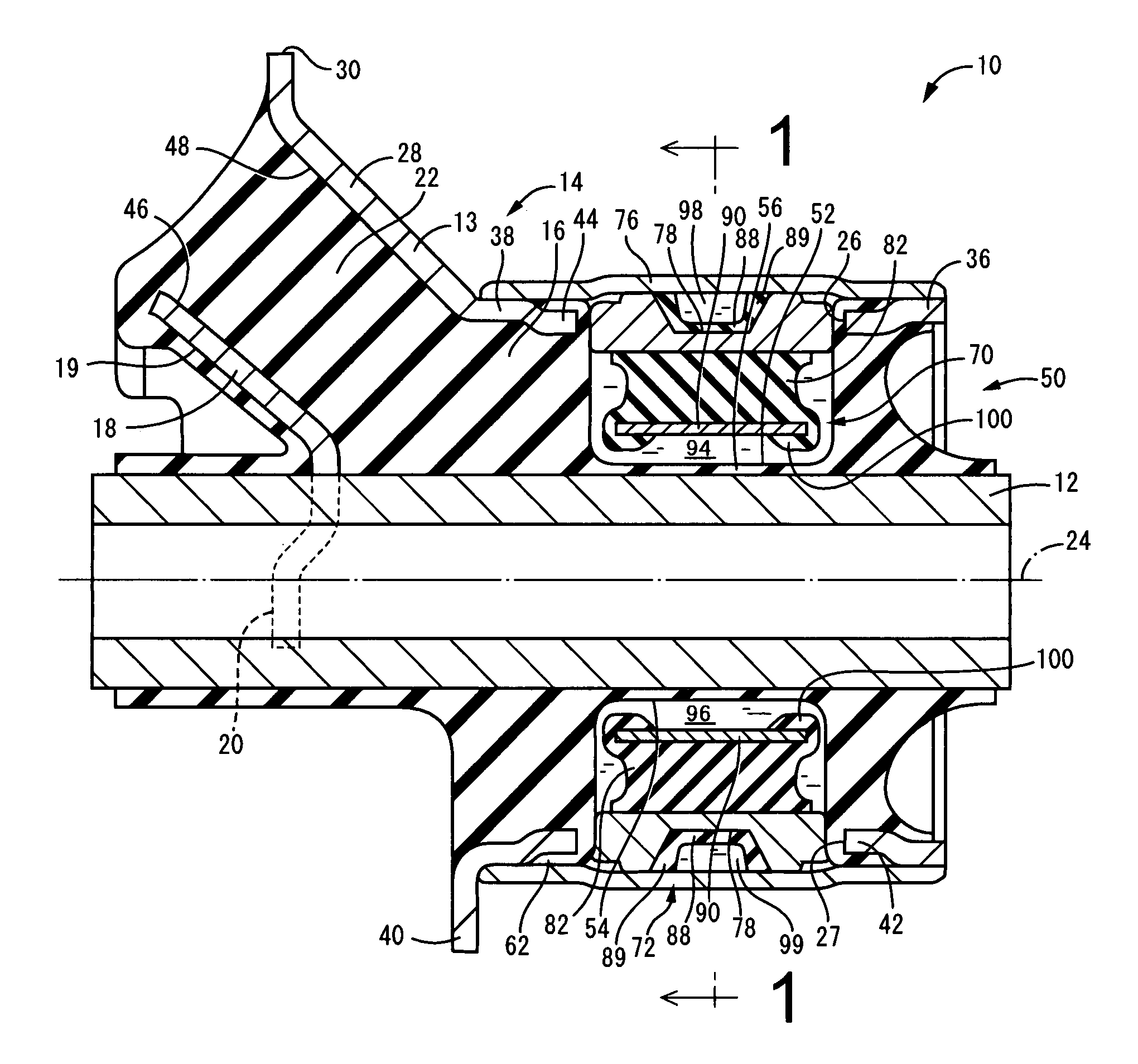
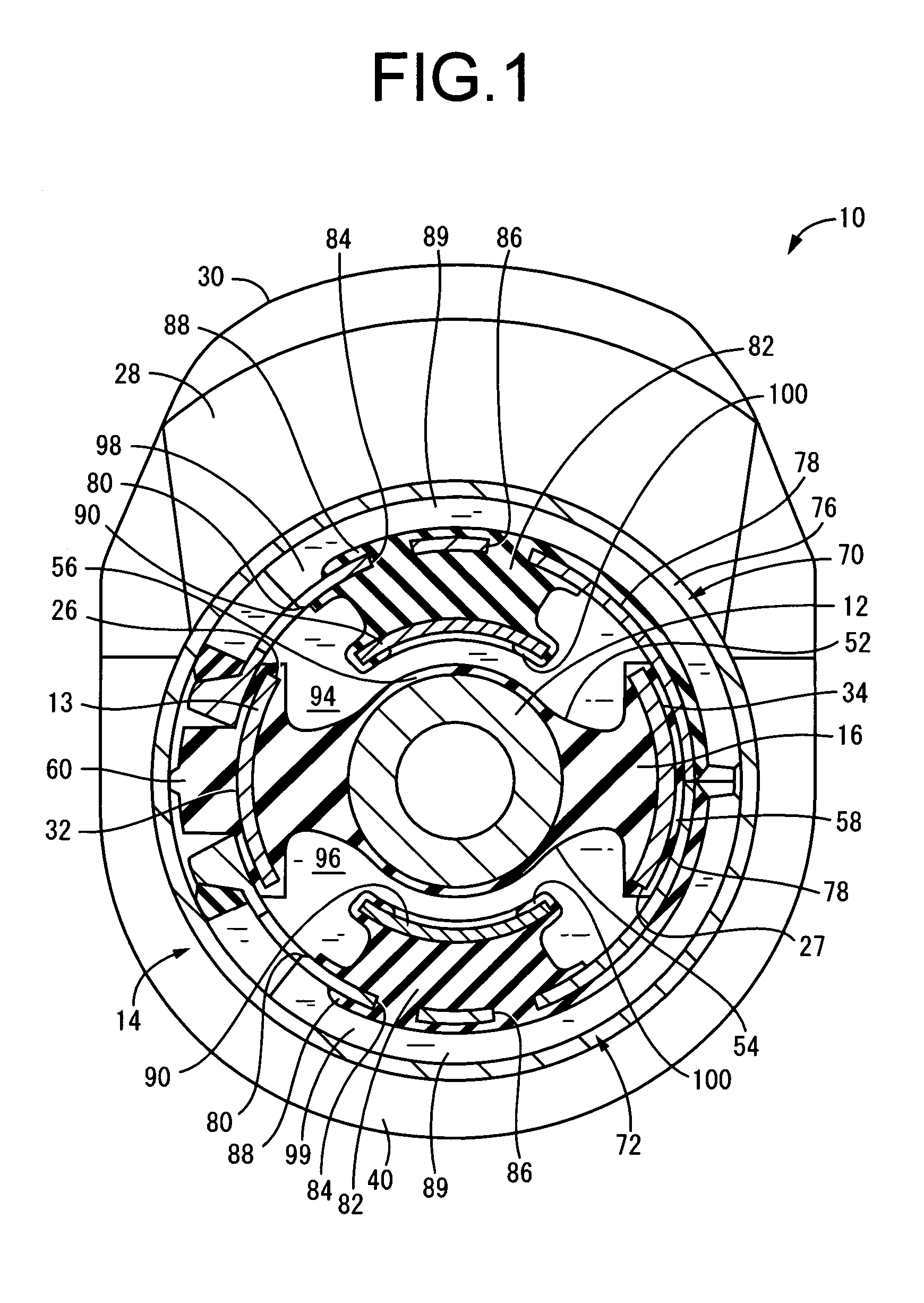
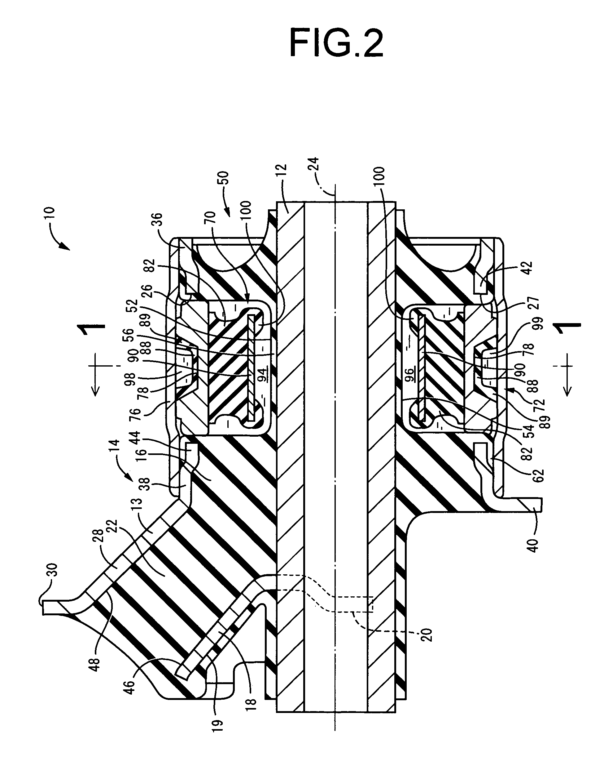
[0041]Referring first to FIGS. 1 and 2, shown is a toe-correction bushing 10 according to one preferred embodiment of a fluid filled cylindrical vibration-damping device of the invention. The toe-correction bushing 10 includes an inner shaft member in the form of a metallic inner sleeve member 12, a metallic outer sleeve member 14 disposed about the inner sleeve member 12 with a diametric spacing interposed therebetween, and a rubber elastic body 16 interposed between the inner and outer sleeve members 12, 14 for elastically connecting these members together. The outer sleeve member 14 is composed of a metallic sleeve 13 and a metallic outer fitting sleeve 76.

[0042]More specifically, the inner sleeve member 12 has a thick-walled, small diameter cylindrical configuration. At one axial end portion of the inner sleeve member 12 (the left hand side as seen in FIG. 2), is bonded a fixing plate 18 of curved fun-like configuration. The fixing plate 18 is a pressed metallic member of curved...


PUM


Abstract

A fluid-filled cylindrical vibration damping device comprising: an elastic body connecting an inner shaft member and an outer sleeve member; a non-compressible fluid-sealing region formed between the inner shaft member and the outer sleeve member; a stop rubber member disposed within the fluid-sealing region and projecting form one of the inner shaft member and the outer sleeve member toward an other of the inner shaft member and the outer sleeve member; and a rigid restricting member bonded to a projecting end portion of the stop rubber member. The stop rubber member extends to a front surface of the rigid restricting member so as to form an abutment rubber projecting from an outer peripheral portion of the front surface so that the projecting end portion of the stop rubber member is brought into abutting contact with the other of the inner shaft member and the outer sleeve member with the abutment rubber.

Description

INCORPORATED BY REFERENCE[0001]The disclosure of Japanese Patent Application No. 2003-155323 filed on May 30, 2003 including the specification, drawings and abstract is incorporated herein by reference in its entirety.BACKGROUND OF THE INVENTION[0002]1. Field of the Invention[0003]The present invention relates generally to a cylindrical vibration damping device usable as suspension bushings, engine mounts, body mounts, differential mounts, sub-frame mounts and the like, and more particularly to a cylindrical vibration damping device of fluid-filled type, which is capable of exhibiting vibration damping effects on the basis of flow action of non-compressible fluid sealed in a fluid sealing region enclosed therein, and which includes a stop rubber member installed within the fluid sealing region.[0004]2. Description of the Related Art[0005]A fluid filled cylindrical vibration damping device is known as one type of vibration damping couplings or mounts interposed between two components...

Claims


Application Information

Patent Timeline
Patent Type & Authority Patents(United States)
IPC IPC(8): F16F13/00B60K5/12F16F13/08F16F13/14F16F13/16
CPCF16F13/16F16F13/1409
Inventor ITO, TATSUYA
Owner SUMITOMO RIKO CO LTD
Learn More