
Method for regulating the speed of a drive motor

a technology of drive motor and speed regulation, which is applied in the direction of gearing control, fluid gearing, couplings, etc., can solve the problems of consumption-optimized range, and achieve the effect of low control-technical and regulation-technical requirements and low manufacturing costs

Inactive Publication Date: 2006-09-05
VOITH TURBO GMBH & CO KG
View PDF7 Cites 8 Cited by
  • Summary
  • Abstract
  • Description
  • Claims
  • Application Information

AI Technical Summary

Benefits of technology

[0004]The purpose of the invention is thus to develop a process for controlling the rotational speed of a drive motor in such a way that the disadvantages mentioned are prevented and if necessary, the consumption-optimized ranges, especially in the use of drive motors in the form of internal combustion engines, optimal from the standpoint of the energy content, can be reached in the performance characteristics of the drive motor during the start up period. The solution according to the invention is characterized by a low control-technical and regulation-technical requirement, as well as a low manufacturing expense.
[0009]The solution according to the invention offers the advantage that in addition to an open controllability of energy-optimized and consumption-optimized operating points in the performance characteristics of the drive motor in the embodiment of the drive motor as an internal combustion engine, a transfer of high torques is readily possible at low rotational speeds and the power of the drive motor that is to be provided, that is necessary for this and that can be transmitted, can be kept low.
[0016]In a further embodiment, the process according to the invention is a component of the controlled system of a control for the power output of the drive motor. This offers the advantage of simple realization of an outside control of the power requirement of the drive motor without direct influence of the drive motor, in particular, without required control of the power output stage, which leads to a reduction of the control-technical and regulation-technical expense.
[0017]In an advantageous embodiment based on this further development, this process forms a portion of the control system for the adjustment of a constant and temporally independent holding moment for the holding function of a machine. By this special control function, the conventional brake devices, for example, in keeping a vehicle on a slope, can be relieved.

Problems solved by technology

This means, however, for embodiment of the drive motor as an internal combustion engine, that the consumption-optimized range in the performance characteristics of the motor, and thus an operating method that is low in hazardous materials, is not achieved and furthermore, for the transfer of high torque a correspondingly high power drive motor is always necessary.

Method used


Image

  • Method for regulating the speed of a drive motor
  • Method for regulating the speed of a drive motor
  • Method for regulating the speed of a drive motor

Examples


Embodiment Construction

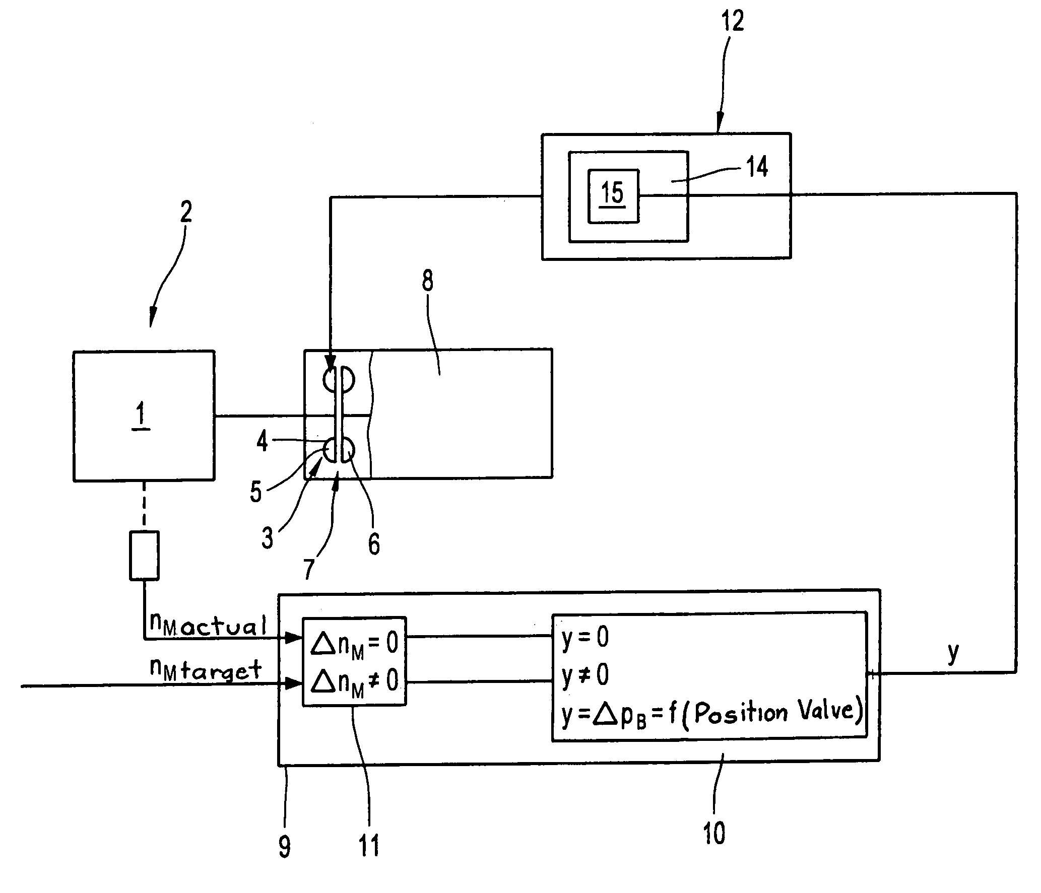
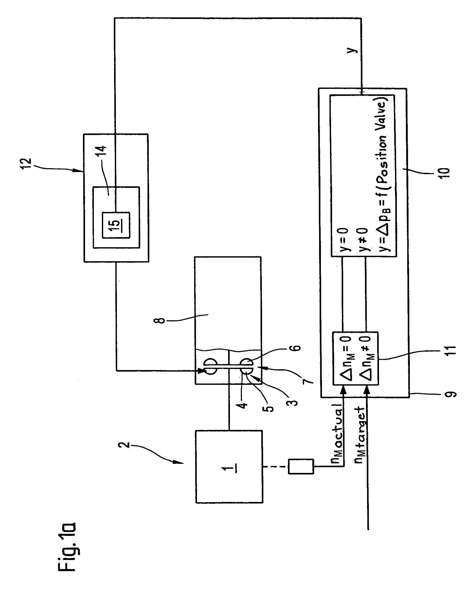
[0033]FIG. 1a shows in a schematically simplified diagram using a block switching diagram, the fundamental principle of a process according to the invention for controlling the rotational speed of a drive motor 1 in a drive train 2 during the start up period. The drive train 2 includes in the process at least one start up element 3 that can be coupled at least indirectly to the drive motor 1 and that is designed as a hydrodynamic coupling 4, including at least one primary blade wheel 5 functioning as a pump wheel and a secondary blade wheel 6 functioning as a turbine wheel, which form with each other at least one toroid-shaped working space 7. The drive motor 1 is preferably designed as an internal combustion engine in motor vehicles in the preferred usage of the process according to the invention. However, embodiments as electric motors are also conceivable. The starter element is preferably integrated in a gear structural unit 8.

[0034]According to the invention, the rotational spe...


PUM


Abstract

The invention involves a process for controlling the rotational speed of a drive motor during a start-up period, in a drive train, containing at least one starter element that can be coupled to the drive motor, in a rotationally fixed manner, in the form of a hydrodynamic coupling, containing a primary blade wheel and a secondary blade wheel, which form together at least one toroid-shaped working space. According to the invention, the rotational speed of the drive motor is set as a function of the power that can be consumed by the hydrodynamic coupling. The consumable power can be controlled or regulated.

Description

BACKGROUND OF THE INVENTION[0001]The invention involves a process for controlling the rotational speed of a drive motor.[0002]Processes for controlling the rotational speed of a drive motor, in particular, during the start up period, in a drive train, in particular for use in motor vehicles, including at least one drive motor and a start up element that can be coupled with it, at least indirectly, are known in a multitude of different embodiments with regard to the variables triggering the controlling operation, i.e. the input variables of the control device, the dependence of the control variables on other variables and the correcting variables. It is generally known that, in drive trains of motor vehicles, including an intemal combustion engine, especially Otto or diesel engines, and a start up element that can be mechanically or hydrodynamically coupled to them, as a correcting variable for the rotational speed control of the drive motor, a variable is formed that at least indire...

Claims


Application Information

Patent Timeline
Patent Type & Authority Patents(United States)
IPC IPC(8): F16D33/06F02D45/00B60W10/02B60W10/06B60W30/18F02D29/00F16D33/16F16H61/14F16H61/64
CPCB60W10/02B60W10/06B60W30/184F16D33/16F16H61/64F16H2312/02B60W2710/0644
Inventor KLEMENT, WERNERVOGELSANG, KLAUSEDELMANN, PETERHOLLER, HEINZFRIEDRICH, JURGENKERNCHEN, REINHARD
Owner VOITH TURBO GMBH & CO KG
Learn More