Modular waste water treatment system

Active Publication Date: 2006-08-29
ICM +1
View PDF62 Cites 21 Cited by
  • Summary
  • Abstract
  • Description
  • Claims
  • Application Information

AI Technical Summary

Benefits of technology

[0008]Accordingly, it is an object of this invention to provide an improved modular, biological, waste treatment system that can be fabricated off site and easily transported to a desired location in a minimum number of transportable units. Another object of this invention is to provide an improved modular anaerobic, biological waste treatment system that has a standard support equipment module including components sized to accommodate one or more bioreactors, so that a system, once installed can be easily and inexpensively expanded to accommodate a larger number of bioreactors thereby multiplying the capacity of the waste treatment system with a minimum of additional cost. Yet another object of this invention is to provide a waste treatment system that has its components placed within a small area so that they are easily and quickly accessible to an operator.
[0009]These and other objects of the invention are attained in an improved, modular, anaerobic, waste water treatment system for removing organic waste from waste water to produce treated water or effluent that is suitable for re-use or further treatment prior to release. The system includes a bioreactor support module and at least one anaerobic bioreactor. The bioreactor support module includes components necessary for receiving waste water, mixing the waste water with bioreactor recycle water and otherwise supporting the operation of one or several bioreactors. The bioreactor support module includes a frame sized for over-the-road transport via truck to which is mounted a recycle tank, a recycle pump, a effluent discharge pump, a decarbonator, a bio-gas scrubber, a flare, a nutrient tank and a control panel as well as appropriate in-line level and flow control devices which maintain flow, temperature and pH within the system. The recycle tank receives waste water and formulates a mixture from waste water, recycled treated water produced by the bioreactors and nutrients which are mixed and fed back to the bioreactors. Like the other components in the bioreactor support module, the recycle tank is preferably sized to support the operation of up to six bioreactors but may also be sized to support more bioreactors. Within the nutrient tank, a mixture is formulated that includes nutrients required by the anaerobic organism present in the bioreactors. A nutrient feed pump responds to signals from the control panel, as the control panel monitors the amount of waste water fed into the system and conveys the amounts of nutrients into the recycle tank that are needed to sustain the microbial cultures in the bioreactors. The amount, temperature and pH of the liquid in the recycle tank are also monitored and controlled by the control panel. The control panel responds to values outside pre-determined limits by changing the feed rates in lines leading to the recycle tank. The control panel may activate a valve to introduce a caustic solution into the recycle tank to adjust pH. The control panel may also cause sparge steam to enter the recycle tank to increase recycle tank temperature to a temperature within an optimum range. Accordingly, the control panel functions to insure that the mixture received by the bioreactors from the recycle tank is optimized for the microbial cultures in the bioreactors. The control panel also monitors the level in the recycle tank and adjusts the discharge from the system to maintain a pre-determined level in the recycle tank.

Problems solved by technology

Since each component must be placed and installed on site, the cost of adding such a system capable of processing on the order of thousands of pounds of dissolved organic waste per day can be significant.
Such a custom designed system would often require significant redesign in order to expand or enlarge a system to process larger amounts of waste.

Method used


Image

  • Modular waste water treatment system
  • Modular waste water treatment system
  • Modular waste water treatment system

Examples


Embodiment Construction

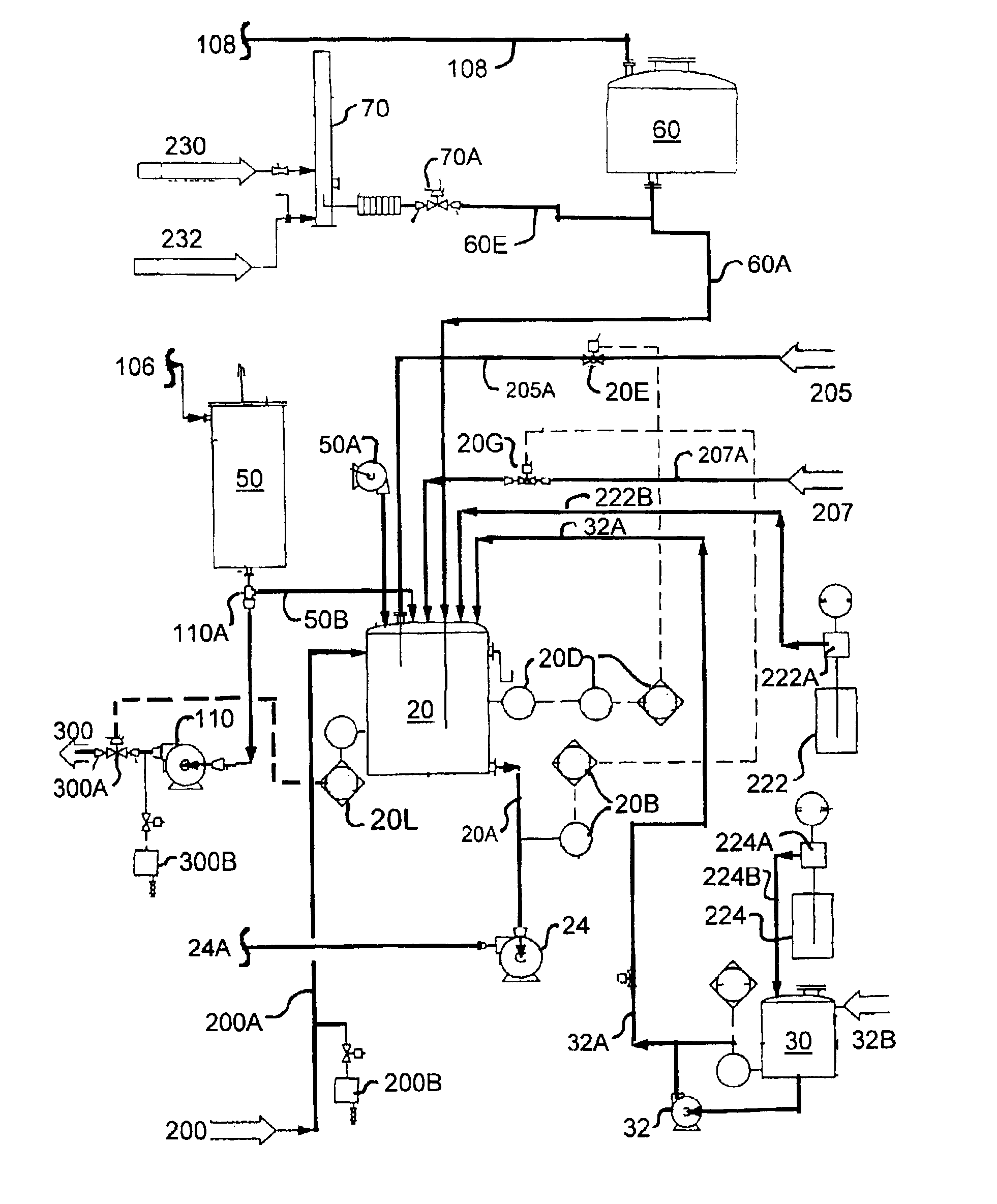
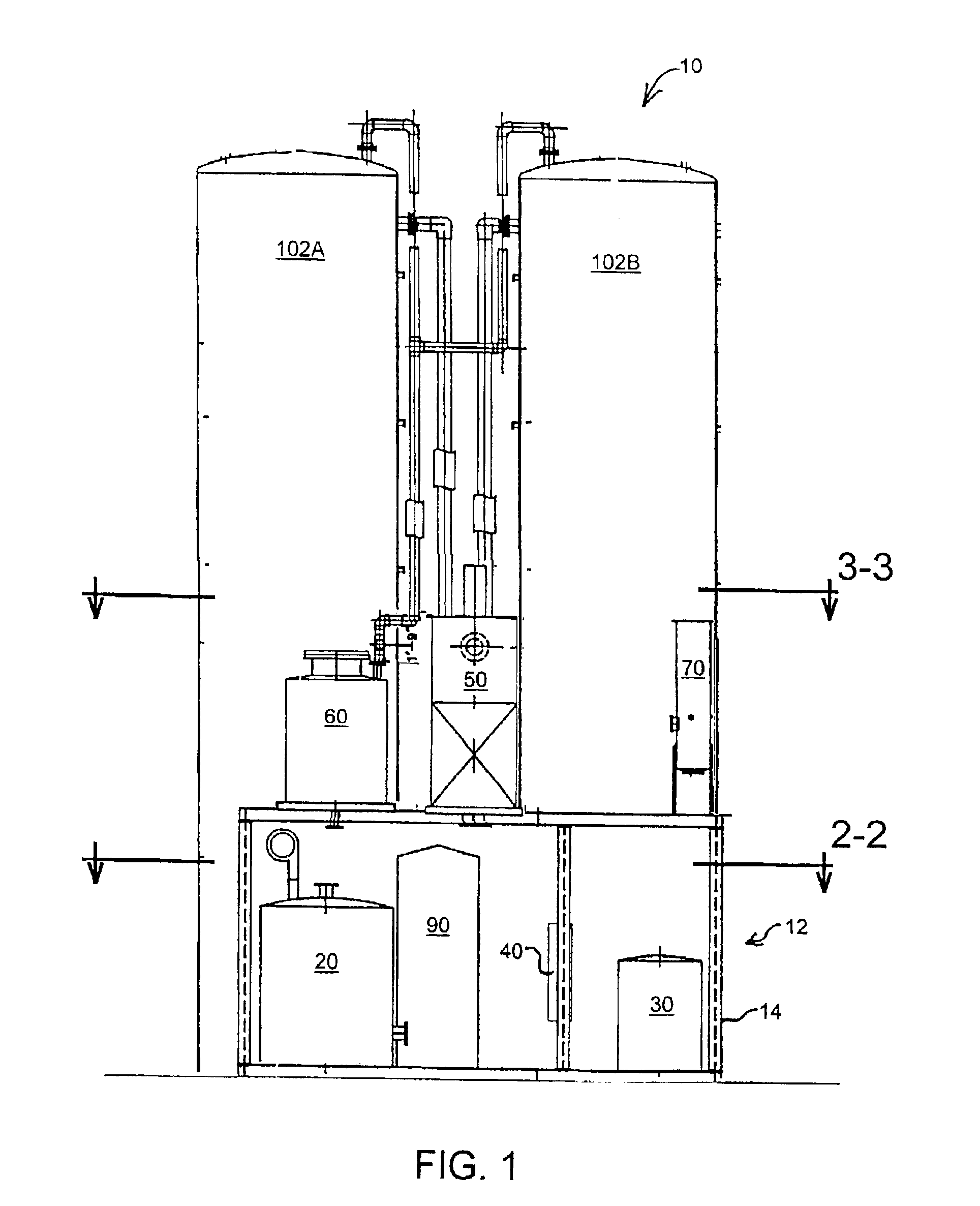
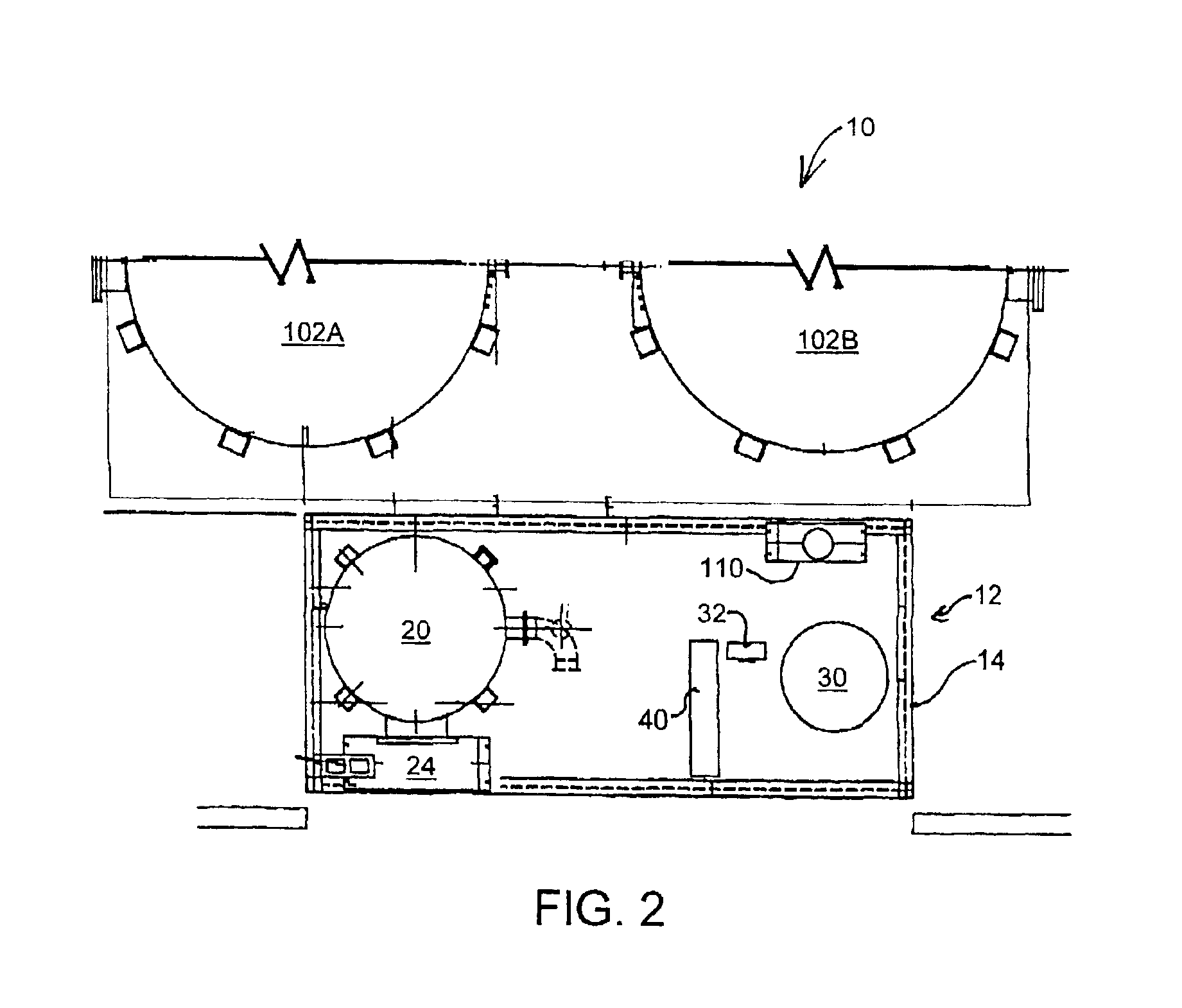
[0020]Turning now to the drawings, wherein like reference numerals identify identical or corresponding elements, and more particularly to FIG. 1 thereof, a modular waste water treatment system 10 is shown including a bioreactor support module 12 and bioreactors 102A and 102B.

[0021]Bioreactor support module 12 is generally a transportable module. Preferably, bioreactor support module 12 houses all of the control equipment for treatment system 10, systems for adding needed nutrients and chemicals, pumps for re-circulation and product discharge and heat control systems required to maintain appropriate operating temperatures. Bioreactor support module 12 includes a frame 14 to which is mounted a number of items of equipment. Frame 14 is preferably sized to fit on the trailer bed of a large tractor trailer for highway transport and is preferably fabricated from structural steel. The items of equipment mounted on the upper level of frame 14 may be removed temporarily during highway transp...


PUM

PropertyMeasurementUnit
Temperatureaaaaaaaaaa
Transport propertiesaaaaaaaaaa

Abstract

The modular waste water treatment system receives waste water from a waste water source containing organic waste and produces a treated water effluent. The modular system includes bioreactors and a bioreactor support module. The bioreactors receive a waste water mixture from the bioreactor support module and produce treated water substantially free of organic waste. The bioreactor support module is a transportable unit fabricated upon a frame adapted for transport by a truck upon a public roadway. The bioreactor support module includes items of equipment needed for conditioning waste water for intake by the bioreactors, items of equipment for receiving, processing and discharging treated water from the bioreactors and may include other items of equipment for receiving and processing other byproducts from the bioreactors. The transportable bioreactor support module is sized to support the operation of between one and preferably as many as six bioractors. Accordingly, the modular waste water treatment system can be fabricated off site in a controlled shop environment, transported to a site, placed at a site and even later expanded to include additional bioreactors for increased capacity with a minimum of cost, time and effort.

Description

CROSS REFERENCE TO A RELATED APPLICATION[0001]This application claims the benefit of U.S. Provisional Patent Application No. 60 / 368,773 filed 29 Mar. 2002.FIELD OF THE INVENTION[0002]This invention relates to a modular system having at least one bioreactor for the anaerobic treatment of waste water and a bioreactor support module that houses support equipment for operating one or more bioreactors.BACKGROUND OF THE INVENTION[0003]Anaerobic waste water treatment provides a means for converting dissolved organic waste into methane and carbon dioxide. More particularly, anaerobic waste water treatment is often referred to as a pre-treatment process since the discharge from an anaerobic waste water treatment process often needs further treatment prior to discharge into the environment. Dissolved organic waste in a volume of waste water is often measured by “chemical oxygen demand” or “COD”. COD is usually given as a unit weight per unit volume or may be given as a unit weight in a given ...

Claims


Application Information

Patent Timeline
IPC IPC(8): C02F3/00B01D53/14
CPCB01D53/52C02F3/006C02F3/2806Y02E50/343C02F2209/02C02F2209/06C02F2203/008Y02E50/30Y02W10/10
Inventor RUOCCO, JOSEPH JOHNRUSSELL, PAUL JOHN
Owner ICM
Why Eureka
Try Eureka