
Cyclone separating apparatus and vacuum cleaner equipped with the same

a technology of separating apparatus and vacuum cleaner, which is applied in the direction of auxillary pretreatment, cleaning filter means, separation processes, etc., can solve the problems of poor cleaning efficiency, parts increase, manufacturing costs increase, etc., and achieve the effect of preventing deterioration of suction force and improving suction efficiency

Inactive Publication Date: 2006-08-29
SAMSUNG GWANGJU ELECTRONICS CO LTD
View PDF18 Cites 63 Cited by
  • Summary
  • Abstract
  • Description
  • Claims
  • Application Information

AI Technical Summary

Benefits of technology

[0008]The present invention was made to overcome the above-mentioned problems of the related art. Accordingly, it is an object of the present invention to provide a compactly structured cyclone separating apparatus capable of improving suction efficiency using a plurality of conventional cyclone dust collecting apparatus, and preventing deterioration of a suction force, and, a vacuum cleaner equipped with the same.

Problems solved by technology

First, connection of the first cyclone to the auxiliary cyclone is so complex that a suction force generated at a cleaner body is not transmitted well, thus causing a poor cleaning efficiency. In addition, the first and the auxiliary cyclones are not disposed in a compact arrangement. Accordingly, the cyclone separating apparatus and the vacuum cleaner are bulky. This causes inconvenience of keeping the vacuum cleaner when it is not in use, and handling the same during a cleaning work. Further, since a connection path between the first and the auxiliary cyclones is complex, a manufacturing process becomes complicated, and accordingly, required parts increase. Therefore, manufacturing costs also increase.
Thus, a heretofore unaddressed need exists in the industry to address the aforementioned deficiencies and inadequacies.

Method used


Image

  • Cyclone separating apparatus and vacuum cleaner equipped with the same
  • Cyclone separating apparatus and vacuum cleaner equipped with the same
  • Cyclone separating apparatus and vacuum cleaner equipped with the same

Examples


Embodiment Construction

[0020]Hereinafter, embodiments of the present invention will be described in detail with reference to the accompanying drawings.

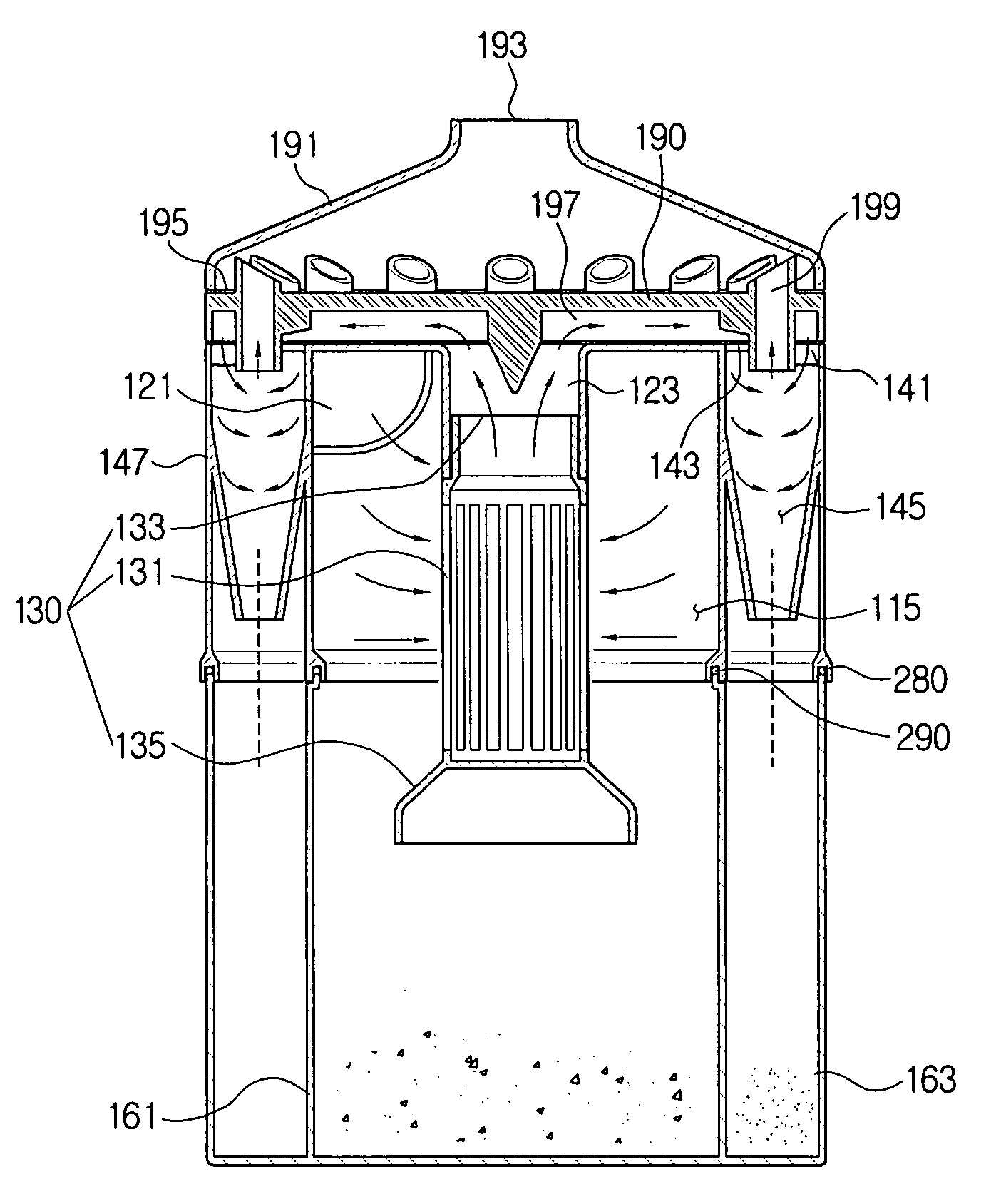
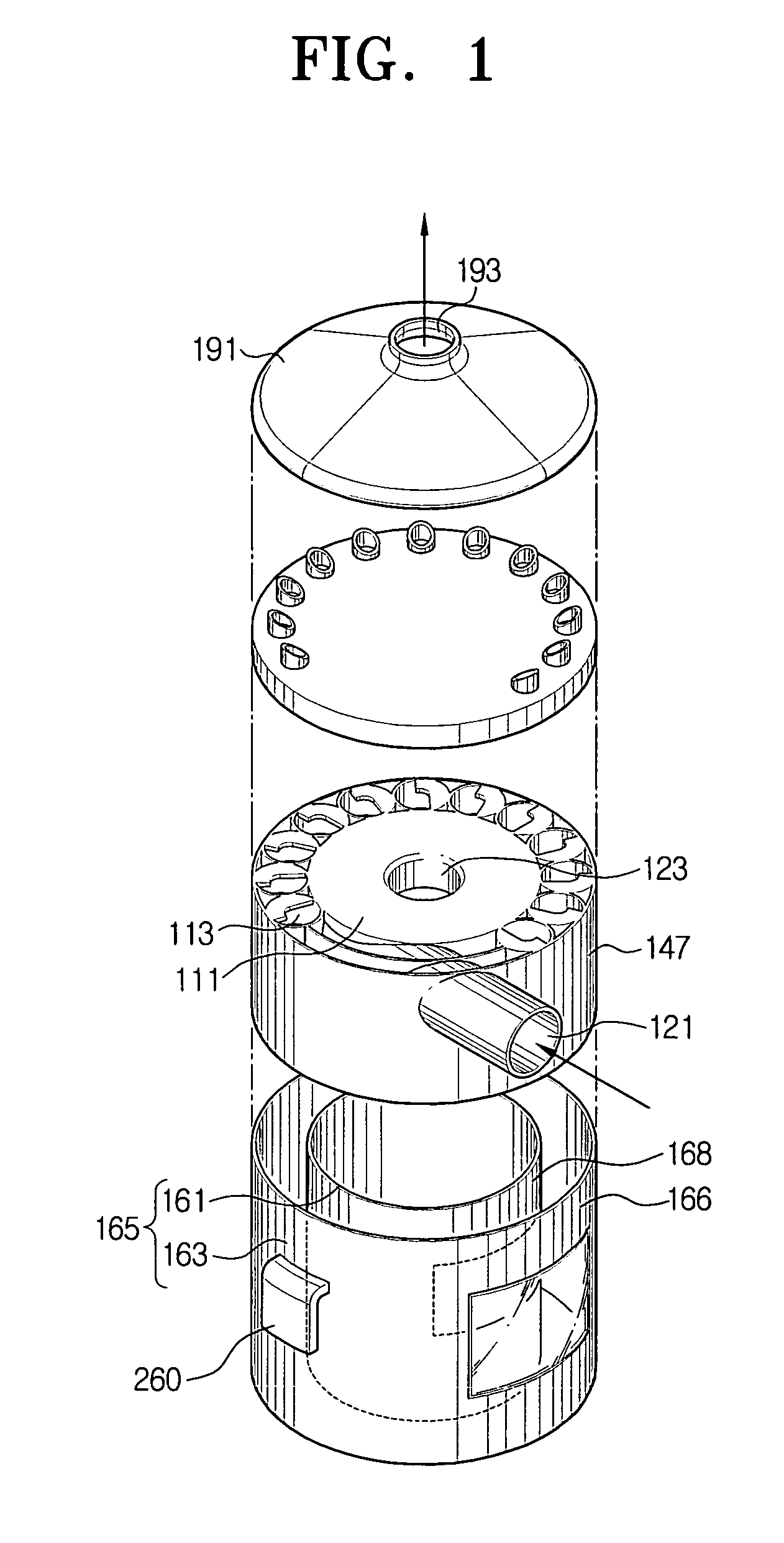
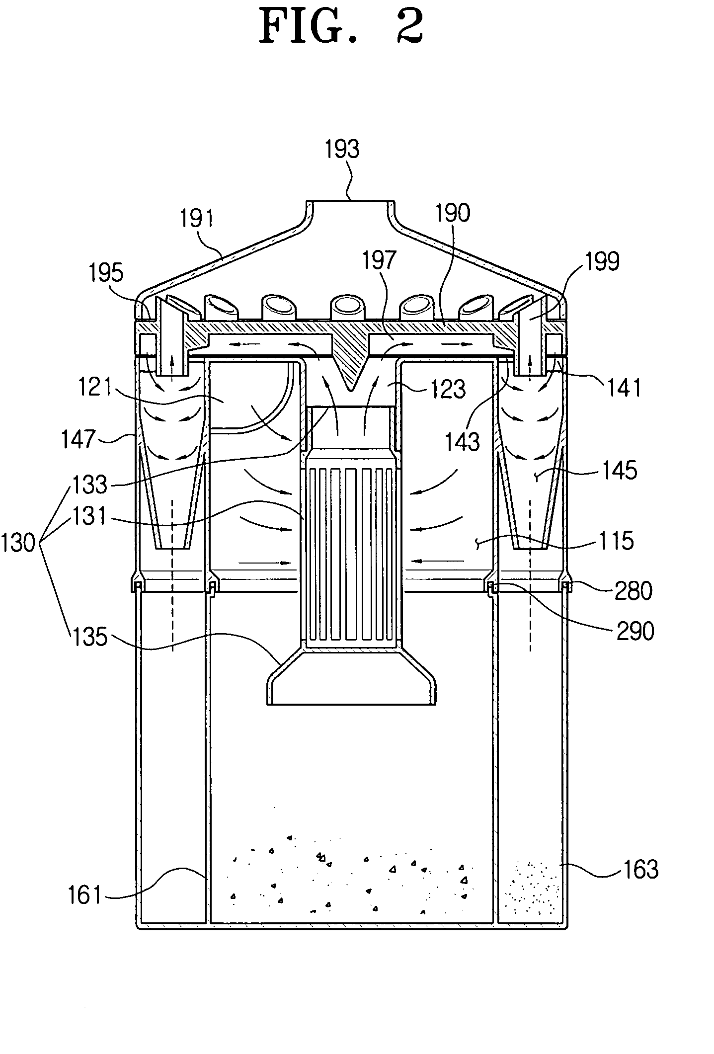
[0021]Referring to FIGS. 1–3, the cyclone separating apparatus according to the present invention includes a first cyclone 111, a plurality of second cyclones 113, an inflow and outflow cover 190 disposed above the first cyclone 111 and the second cyclones 113, a cyclone cover 191, and a dust collecting unit 165. The plurality of second cyclones 113 are formed on an outer circumference of the first cyclone 111, enclosing the first cyclone 111. The first cyclone 111 and the respective second cyclones 113 are integrally formed, and cyclone partitions 250 are disposed between the second cyclones 113, as shown in FIG. 3. The cyclone partitions 250 divide spaces between the respective second cyclones 113, and therefore strongly support the cyclone separating apparatus 100 (FIG. 4). A cylindrical chamber wall 147 is disposed around the second cyclones 113, and is...


PUM

PropertyMeasurementUnit
cylindrical shapeaaaaaaaaaa
transparentaaaaaaaaaa
cone shapeaaaaaaaaaa

Abstract

Disclosed is a cyclone separating apparatus, and a vacuum cleaner having the same. The cyclone separating apparatus includes a first cyclone separating dust from dust-ladened air. A plurality of second cyclones centrifugally separate fine dust particles from air which is first separated at the first cyclone. A dust collecting unit detachably connects to the first and the second cyclones. The dust collecting unit separately collects large dust particles separated at the first cyclone, and fine dust particles separated at the second cyclone. Accordingly, a more compact cyclone separating apparatus can be realized with improved suction efficiency and dust collecting efficiency.

Description

REFERENCE TO RELATED APPLICATION[0001]This application claims priority to copending Korean Application No. 2003-63213, filed Sep. 9, 2003, in the Korean Intellectual Property Office, the disclosure of which is incorporated herein by reference.CROSS-REFERENCE TO RELATED APPLICATIONS[0002]This application is related to copending applications entitled “Cyclone Separating Apparatus and Vacuum Cleaner having the same” (Korean Application Nos. 2003-63211, filed Sep. 9, 2003), “Cyclone Dust Separating Apparatus and Vacuum Cleaner having the same” (Korean Application No. 2003-63212 filed Sep. 9, 2003), and “Cyclone Separating Apparatus and Vacuum Cleaner having the same” (Korean Application No. 2003-62520, filed Sep. 8, 2003), whose disclosures are commonly owned by the same assignee as the present application and are entirely incorporated herein by reference.FIELD OF THE INVENTION[0003]The present invention relates to a cyclone separating apparatus and a vacuum cleaner equipped with the sa...

Claims


Application Information

Patent Timeline
Patent Type & Authority Patents(United States)
IPC IPC(8): B01D45/12A47L9/16B04C5/185B04C5/26
CPCA47L9/1625A47L9/1641B04C5/26B04C5/185Y10S55/03A47L9/16
Inventor OH, JANG-KEUN
Owner SAMSUNG GWANGJU ELECTRONICS CO LTD
Learn More