
Increased heat exchange in two or three phase slurry

a heat exchange and liquid continuous technology, applied in the field of increased heat exchange in a two or three phase, liquid continuous slurry, can solve the problems of limiting the hydrocarbon production reducing the efficiency of the reaction, and limiting the production of the reactor at a given temperature, so as to maximize the production of higher molecular weight hydrocarbon products, increase heat exchange, and increase heat exchange

Inactive Publication Date: 2006-08-29
EXXON RES & ENG CO
View PDF27 Cites 24 Cited by
  • Summary
  • Abstract
  • Description
  • Claims
  • Application Information

AI Technical Summary

Benefits of technology

The patent text describes a new heat exchange system for slurries in a reactor, which uses ribbed tubes or conduits with shallow and low aspect ratio heat exchange protuberances. This system provides better heat transfer than conventional systems with finned or plain tubes, resulting in higher production of higher molecular weight hydrocarbon products. The ribs are aligned parallel or spirally along the flow direction of gas bubbles in the slurry. The system can operate at a lower temperature, maximize production of higher molecular weight hydrocarbon products, or increase productivity by increasing the gas bubble flow rate. The heat exchange means are made of metal and have a unique design that distinguishes them from common heat exchange fins. The technical effect of this new system is better heat transfer and improved production of valuable hydrocarbon products.

Problems solved by technology

In such applications, heat transfer limitations between the slurry and indirect heat exchange means for removing or adding heat to the slurry in the reactor, can reduce the efficiency of the reaction and limit the reactor production at a given temperature.
This can limit hydrocarbon production at a given temperature, due to heat transfer limitations between the slurry and the indirect heat exchange cooling means immersed in it, inside the reactor.

Method used


Image

  • Increased heat exchange in two or three phase slurry
  • Increased heat exchange in two or three phase slurry
  • Increased heat exchange in two or three phase slurry

Examples


examples

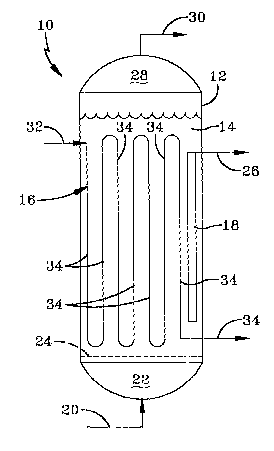
[0027]A hollow, cylindrical column having a diameter of 9¼ inches was constructed of Plexiglasse® It had a porous gas distributor plate fabricated of sintered glass at the bottom, above which was the two or three-phase slurry in which the heat exchange tubes to be evaluated were suspended. The gas distributor was pervious to gas, but not water, with an average pore size of about 45 μm. The static height of the liquid or the liquid and glass bead mixture in the column above the gas distributor plate, prior to introducing the gas flow, was about 60 inches. The column was operated in both two and three phase slurry modes. A three-phase slurry comprising a liquid continuous phase containing gas bubbles and particulate solids, is often referred to as simply a slurry. The gas was introduced into the liquid from a plenum section beneath the porous distributor plate, from which it bubbled up into, through and out the top of the liquid. In the three phase slurry operation mode, glass beads w...


PUM

PropertyMeasurementUnit
aspect ratioaaaaaaaaaa

Abstract

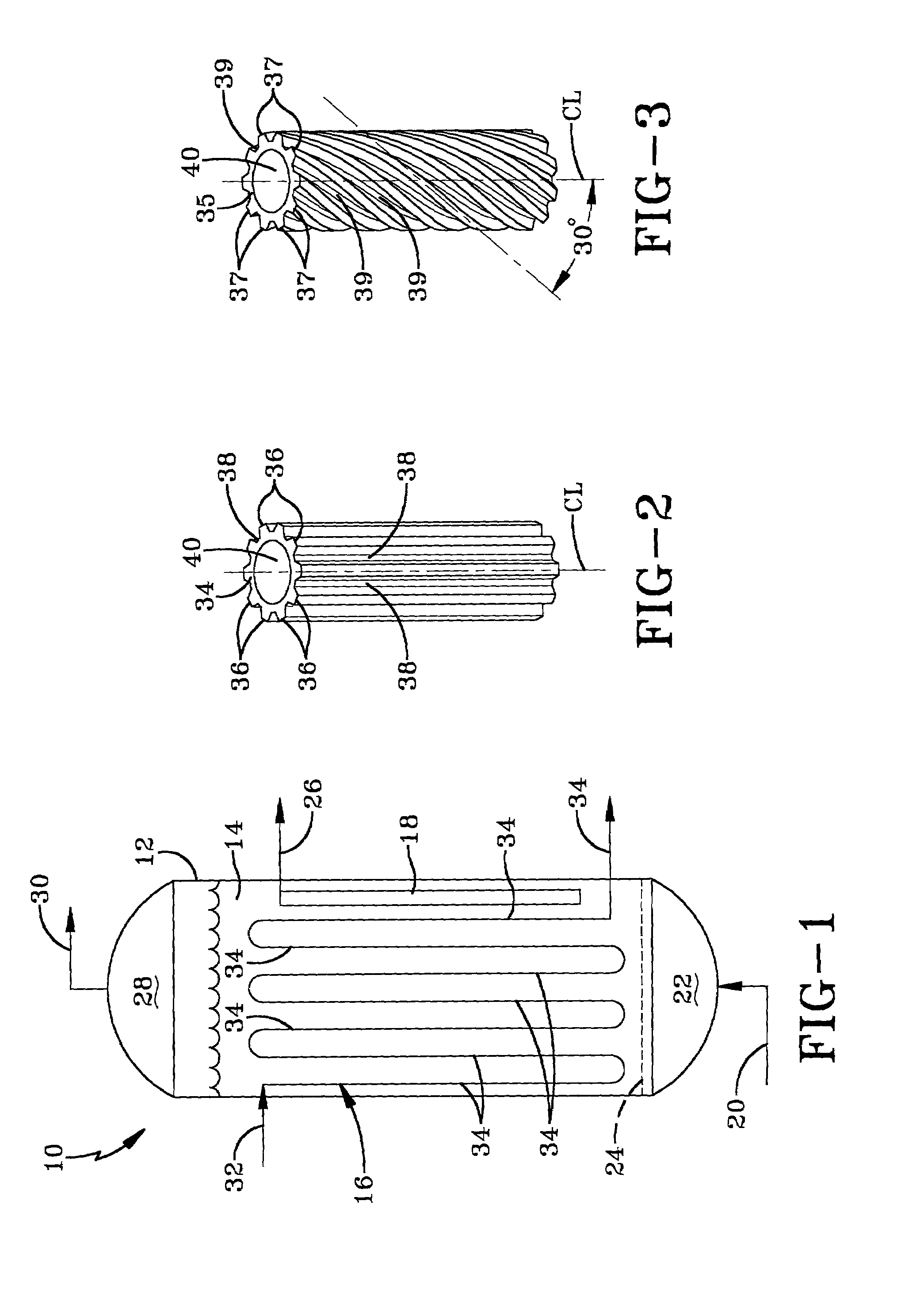
Ribbed heat exchange tubes in which the aspect ratio of the ribs is less than 5, provide greater indirect heat exchange than conventional heat exchange tubes with or without fins, when used in a slurry comprising a liquid phase, in which is dispersed flowing gas bubbles or particulate solids and flowing gas bubbles. The ribs, and typically also the longitudinal axis of the heat exchange tubes, are aligned in a direction parallel to, or spirally along the gas bubble flow direction. This is useful to increase either (i) the productivity of a slurry Fischer-Tropsch hydrocarbon synthesis reactor without an increase in the temperature in the reactor or (ii) increasing the production of higher molecular weight hydrocarbons by reducing the reaction temperature at a given feed conversion.

Description

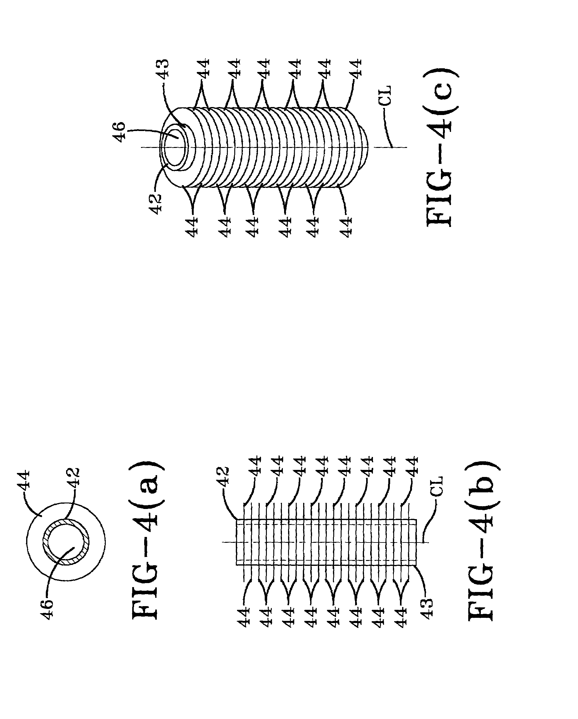
BACKGROUND OF THE DISCLOSURE[0001]1. Field of the Invention[0002]The invention relates to increased heat exchange in a two or three phase, liquid continuous slurry that contains gas bubbles. More particularly, the invention relates to increasing indirect heat transfer into or out of a liquid continuous, two or three phase slurry in a vessel, by using ribbed tube heat exchangers, in which the ribs are aligned generally along the longitudinal axis of the tubes and parallel to the overall flow direction of the gas bubbles, with the aspect ratio of the ribs less than 5 and with the ratio of the base tube O.D. to the rib height greater than 10. This is useful for increasing the productivity of a slurry Fischer-Tropsch hydrocarbon synthesis reactor.[0003]2. Background of the Invention[0004]Chemical processes occurring in two or three phase slurries comprising a slurry liquid in which is dispersed or suspended (i) gas bubbles or (ii) gas bubbles and particulate solids are known and find us...

Claims


Application Information

Patent Timeline
Patent Type & Authority Patents(United States)
IPC IPC(8): F28F13/18F28F1/14F28F1/36F28F19/02F28F9/04F28F1/40B01J8/18B01J8/22C10G2/00F28F1/16F28F1/26
CPCB01J8/1836B01J8/22F28F1/36F28F1/16F28F1/26C10G2/344B01J2208/00132C10G2/00F28F1/42
Inventor CHANG, MINBAUMAN, RICHARD FRANK
Owner EXXON RES & ENG CO
Learn More