
Method of making a glass sheet using controlled cooling

a technology of controlled cooling and glass sheets, applied in glass rolling apparatus, glass tempering apparatus, manufacturing tools, etc., can solve the problems of glass deformation, major challenge to the use of glass substrates, loss of proper registration, etc., to increase the initial cooling increase the rate of glass sheets, and increase the flow of molten glass

Inactive Publication Date: 2009-04-23
CORNING INC
View PDF22 Cites 78 Cited by
  • Summary
  • Abstract
  • Description
  • Claims
  • Application Information

AI Technical Summary

Benefits of technology

[0029]Embodiments of a third aspect of the present invention provide a method for increasing the rate at which a glass sheet is produced by a fusion downdraw machine where the machine comprises a forming wedge and the method comprises (a) increasing the flow of molten glass over the forming wedge, and (b) increasing the initial cooling rate of the sheet as the sheet leaves the forming wedge. In accordance with certain applications of this aspect of the invention, the cooling rate of the glass sheet is reduced in the region of the sheet where the viscosity of the glass making up the sheet increases from 1011 poises to 1014 poises.
[0030]Embodiments of a fourth aspect of the present invention provide a method for increasing the rate at which a glass sheet is produced by a fusion downdraw machine comprising increasing the flow of molten glass through the machine and changing the relative lengths of a viscous, a visco-elastic, and an elastic zone of the sheet.
[0031]Embodiments of a fifth aspect of the present invention provide a method for increasing the rate at which a glass sheet is produced by a fusion downdraw machine comprising increasing the temperature at which substrates are separated from the glass sheet.

Problems solved by technology

Residual stress which may be frozen into the glass, if relieved by cutting the glass into smaller portions, may result in deformation of the glass, and a loss of proper registration.
The evolution from α-Si to ρ-Si has presented a major challenge to the use of a glass substrate.
The construction of a fusion downdraw line requires a substantial capital investment.
Because substrates produced by such a line are typically employed in the manufacture of consumer products (see above), there exists a continual pressure to reduce costs.
Thermal instability of glass substrates used in the production of liquid crystal displays has been a longstanding problem in the art.
Such heat treatments are known as “pre-shrinking” or “pre-compacting.” The heat treatments involve further handling of the substrates thus increasing the chances of damage to the surfaces of the substrates, as well as increasing overall manufacturing costs.
Although this approach does work, it has the serious drawback that it requires longer distances between the root of the isopipe and the location where substrates are separated from the glass sheet.
These longer distances take up additional real estate and capital.
Indeed, due to the physical constraints of existing facilities, this approach to dealing with compaction can limit the maximum flow available to a given glass forming installation.
Another limitation of the fusion draw process as currently practiced relates to the material properties of the glass to be processed.
If the glass has a viscosity lower than about 100,000 poise, the quality of the sheet degrades, e.g. in terms of maintaining the sheet flatness and controlling the thickness of the sheet across its width, and glass sheet thus produced is no longer suitable for display applications.
According to current practice, if a glass composition which has a liquidus viscosity of less than about 100,000 poises is processed under conditions such that the dimensional quality of the glass sheet would be adequate, devitrification may develop on the isopipe and lead to crystalline particulates in the glass sheets.
This is not acceptable for display glass applications.

Method used


Image

  • Method of making a glass sheet using controlled cooling
  • Method of making a glass sheet using controlled cooling
  • Method of making a glass sheet using controlled cooling

Examples


case b

[0126]Start from a lower viscosity (50,000 vs. 130,000 poises) while maintaining a constant spatial temperature profile and flow rate;

case c

[0127]Start from a lower viscosity (50,000 vs. 130,000 poises) at the same flow rate as in case B, and modifying the temperature profile to maintain a given pulling force. In this case a 750° C. temperature 1 m below the root was maintained constant;

case d

[0128]Start from a lower viscosity (50,000 vs. 130,000 poises) while maintaining a constant spatial temperature profile, and modifying the flow rate to maintain a given pulling force.

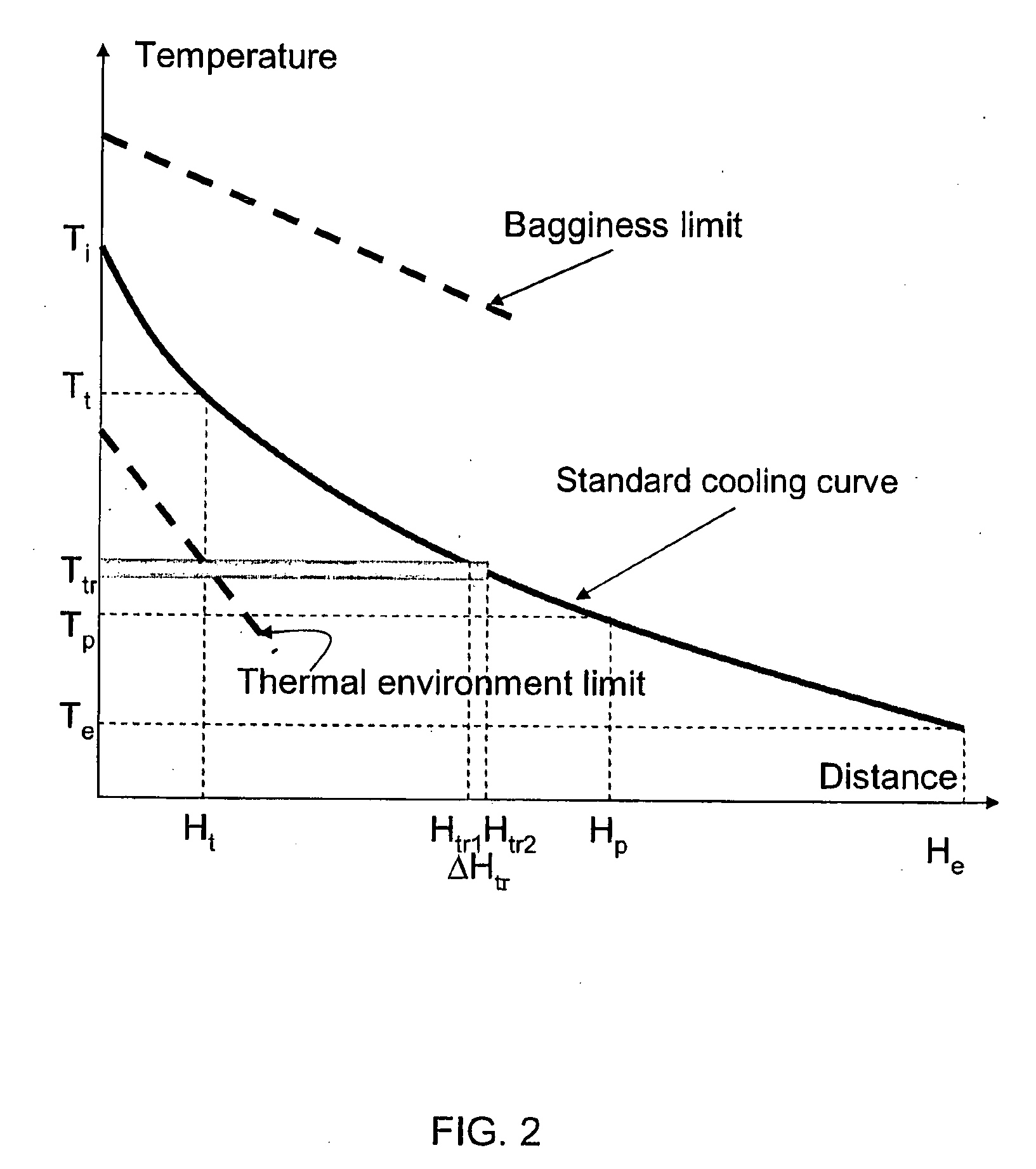
[0129]The results of the above analysis are summarized numerically in the table provided in FIG. 10 and graphically in FIGS. 11-12. As indicated in FIG. 10, decreasing the viscosity from approximately 130,000 as given in the standard Case A to about 50,000 poise in Case B while maintaining essentially the same cooling curve as in the standard case (Case A) results in a decrease in pulling force from 50 N / m to 3.5 N / m, and a very significant increase in the gravity contribution, from 47% to 91%. Thus, the glass sheet formed in accordance with case B is formed with a close to 0 pulling force and may prove unacceptable from a glass quality perspective. That is, the pulling force decrease combined with an increase in the gravity contribution to the pulling force may result in so-called baggy warp of the gla...


PUM

PropertyMeasurementUnit
Temperatureaaaaaaaaaa
Fractionaaaaaaaaaa
Fractionaaaaaaaaaa

Abstract

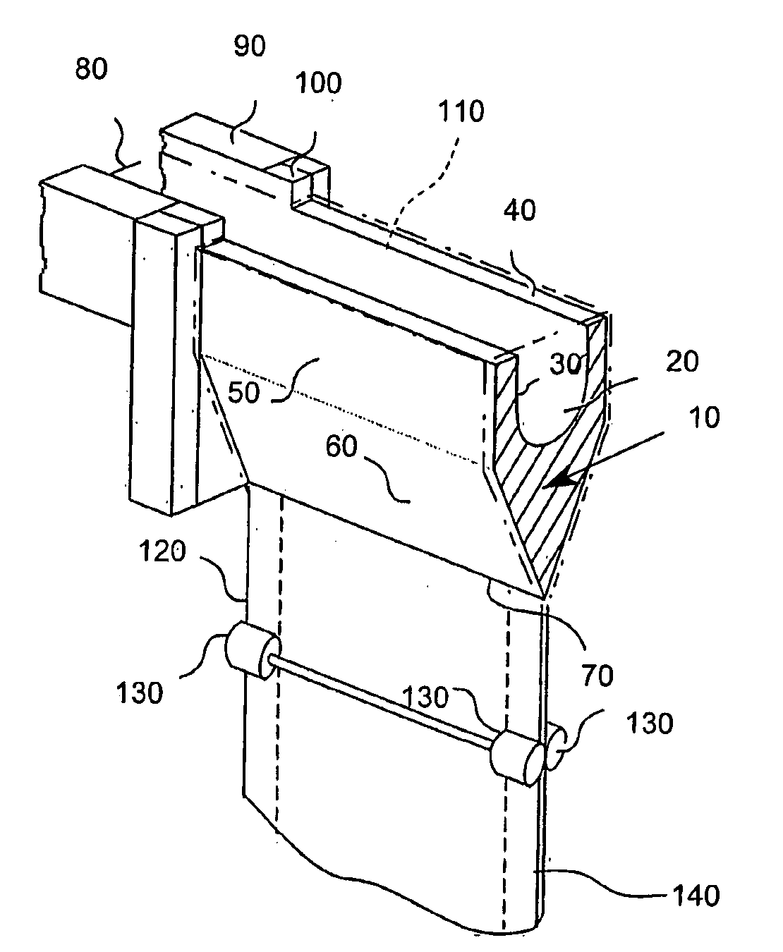
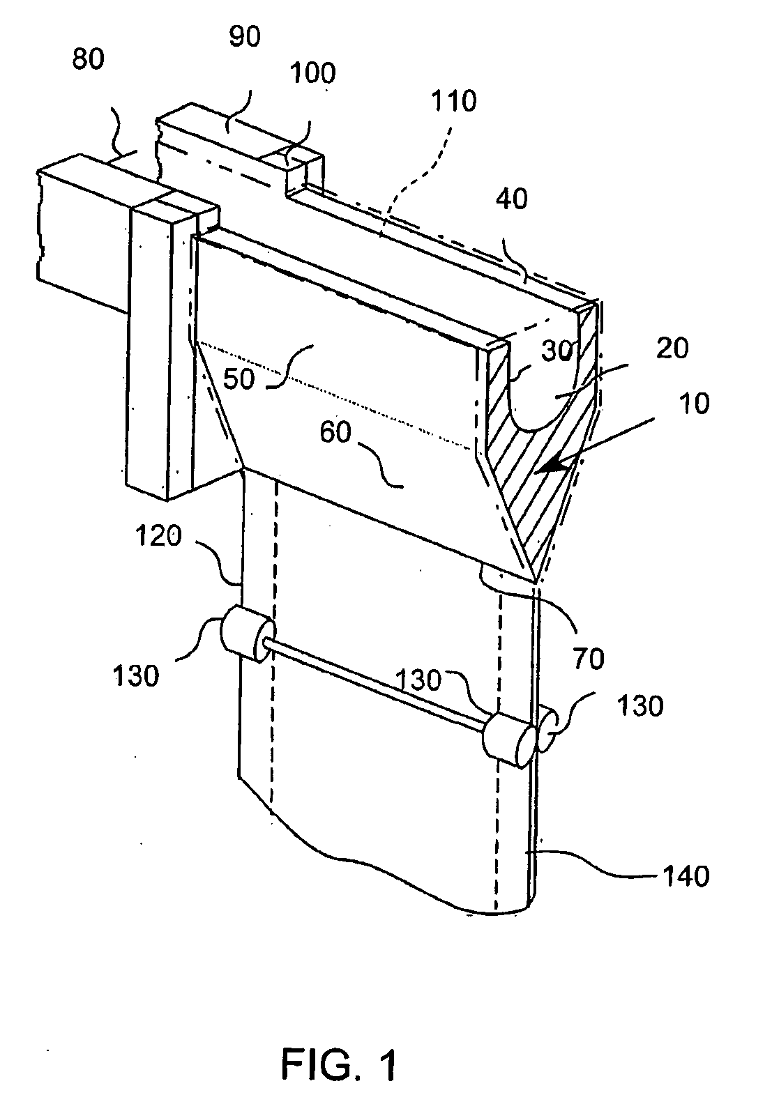
Methods of drawing glass sheet via a downdraw process are provided. In certain aspects, the methods utilize rapid cooling below the root (70) of the forming apparatus (10). Such rapid cooling can, for example, facilitate the use of glass having a liquidus viscosity less than about 100,000 poise. In other aspects, the methods utilize slow cooling between the viscosities of 1011 poises and 1014 poises. Such slow cooling can facilitate the production of glass substrates which exhibit low levels of compaction. In further aspects, substrates are removed from the glass sheet at elevated temperatures which can facilitate increases in the production rates of downdraw machines. In still further aspects, rapid cooling below the root, slow cooling between the viscosities of 1011 poises and 1014 poises, and / or substrate removal at elevated temperatures are combined. Such combinations can facilitate economically effective utilization of downdraw equipment.

Description

BACKGROUND OF THE INVENTION[0001]1. Field of the Invention[0002]This invention is directed to methods of forming a glass sheet (glass ribbon) and, in particular, to methods of forming a glass sheet using controlled cooling between the location where the sheet is formed (e.g., the root of an isopipe) and the location where individual substrates are separated from the sheet (e.g., the location where the ribbon is scored as the initial step of the separation process).[0003]2. Technical Background[0004]Glass display panels in the form of liquid crystal displays (LCDs) are being used in an increasing variety of applications—from hand-held personal data assistants (PDAs) to computer monitors to television displays. These applications require glass sheets which have pristine, defect-free surfaces. LCDs are comprised of at least several thin sheets of glass which are sealed together to form an envelope. It is highly desirable that the glass sheets which comprise these displays do not deform...

Claims


Application Information

Patent Timeline
IPC IPC(8): C03B19/00C03B33/02C03B27/00
CPCC03B17/067C03B17/064Y02P40/57C03B33/02C03B17/06
Inventor ALLAN, DOUGLAS CLIPPINGERBORATAV, OLUS NAILIFILIPPOV, ANDREY V.FREDHOLM, ALLAN MARKKENT, LEONARD R.KLINGENSMITH, LEWIS KIRKOTT, TERRY JAYRHOADS, RANDY LEE
Owner CORNING INC
Learn More