
Optical probe including predetermined emission wavelength based on patient type

a technology of optical probes and wavelengths, applied in the field of optical sensors, can solve the problems of affecting the accuracy of the measurement, and reducing so as to reduce the light energy reaching the detector

Active Publication Date: 2006-08-22
JPMORGAN CHASE BANK NA
View PDF41 Cites 850 Cited by
  • Summary
  • Abstract
  • Description
  • Claims
  • Application Information

AI Technical Summary

Benefits of technology

"The invention is about a new type of sensor that can be used on patients to measure things like blood flow. The sensor is designed to reduce the amount of light that is lost when it reaches the patient's tissue. This is important because it helps to get accurate readings from the sensor. The invention also includes ways to make the sensor compatible with existing patient monitoring devices. Overall, the invention improves the accuracy and reliability of measuring blood flow and other important patient parameters."

Problems solved by technology

Drawbacks arise in reflectance-type sensors when light energy from the LEDs bounces along the surface of the tissue at the measurement site, or otherwise reaches the detector without passing through the tissue.
Such light energy has not been attenuated by the tissue, and therefore, distorts or otherwise provides noise to the energy being received at the detector.
Additionally, reflectance-type sensors present various drawbacks during application, such as, for example, improper positioning on a measurement site, improper securement to the same, or the like.
These drawbacks can increase the likelihood that light energy reaches the detector without having first been attenuated by the tissue.
Monitoring systems can also present drawbacks of backwards compatibility when dealing with newly developed sensor technologies.
Thus, as new sensors are developed and used during patient monitoring, the oximeter may not include an appropriate set of calibration curves to appropriately associate detected energy with the foregoing data.

Method used


Image

  • Optical probe including predetermined emission wavelength based on patient type
  • Optical probe including predetermined emission wavelength based on patient type
  • Optical probe including predetermined emission wavelength based on patient type

Examples


Embodiment Construction

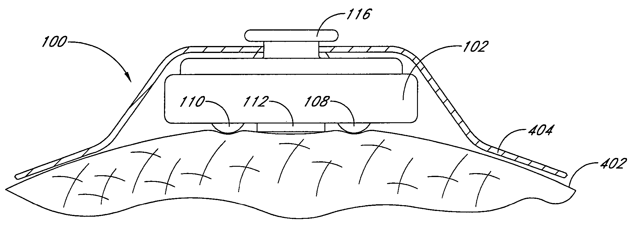
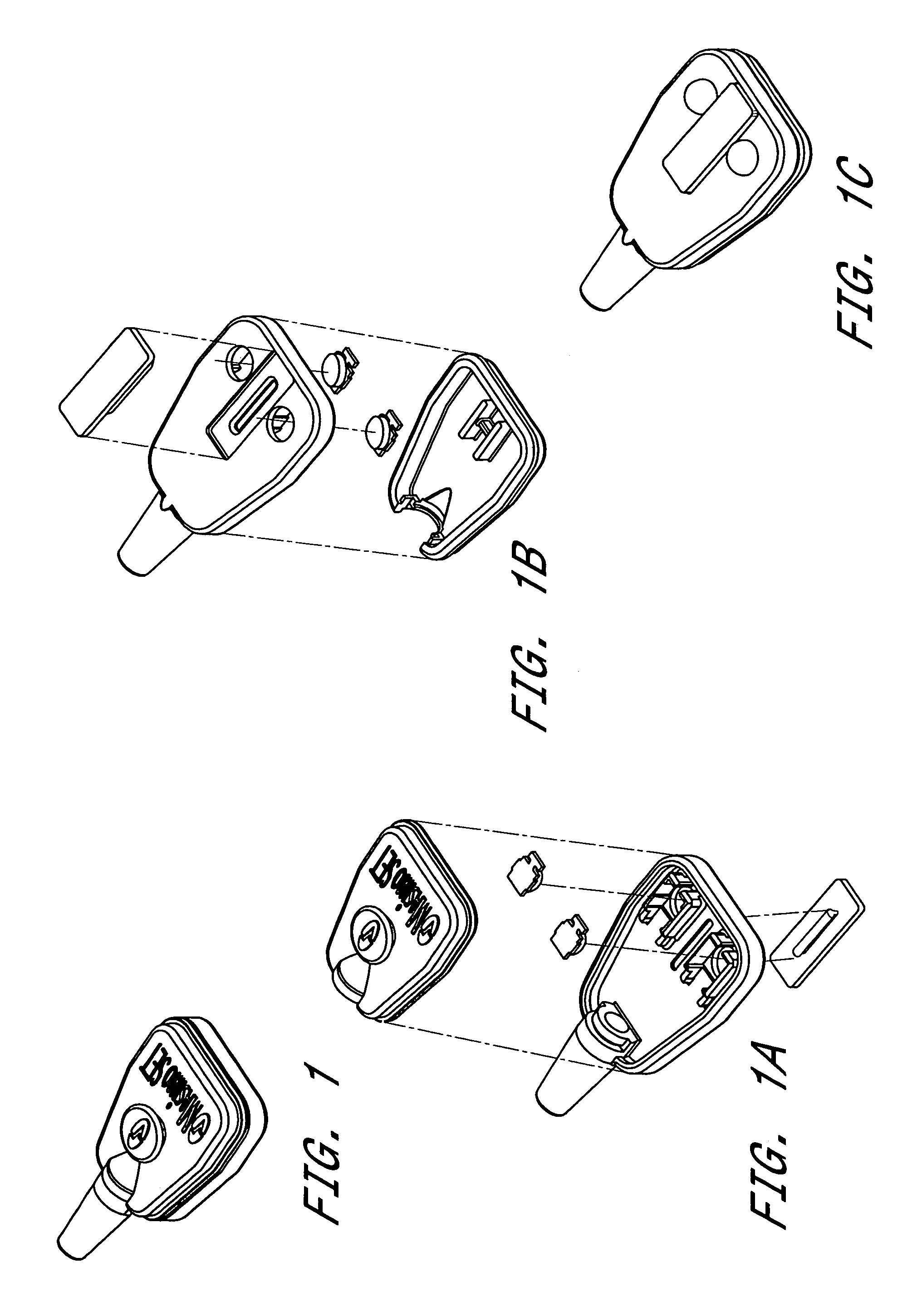
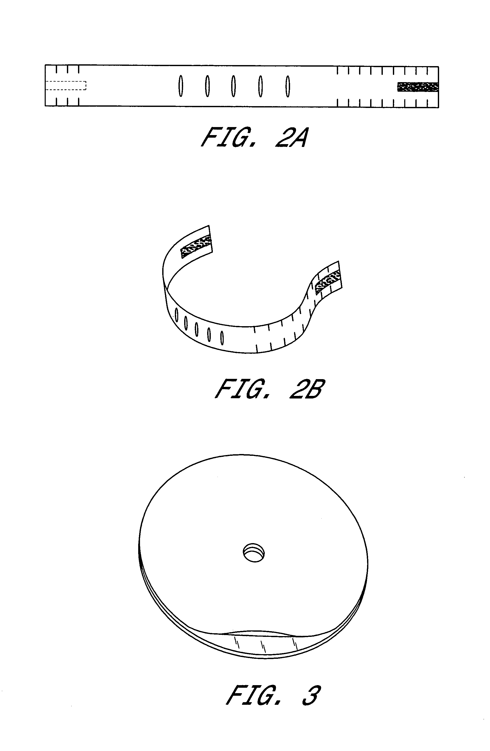
[0017]Aspects of the invention include a reflectance sensor including protruding lenses and a protruding optical barrier. According to one embodiment, one lens houses the one or more emitters and the other lens houses the detector. In addition, the reflectance sensor includes an attachment mechanism which provides sufficient pressure holding the sensor against a measurement site such that the protruding lenses and optical barrier noninvasively recess into the tissue of the measurement site. Thus, when the emitter emits light energy through a first lens recessed into the tissue, the light energy enters the tissue, is attenuated, and is received by the second lens recessed into the tissue and housing the detector. The recessed optical barrier advantageously reduces a potential that the light energy can reach the second lens and then the detector without first being attenuated by the tissue.

[0018]According to one embodiment, the attachment mechanism comprises a wrap such as a headband,...


PUM


Abstract

A reflectance sensor which can be applied to a patient in a manner which reduces the light energy reaching the detector without first being attenuated by the tissue at the measurement site. Moreover, the reflectance sensor includes emitting devices adapted for use in legacy patient monitoring systems.

Description

RELATED APPLICATIONS[0001]The present application claims priority to U.S. Provisional Application No. 60 / 416,492, filed Oct. 4, 2002.FIELD OF THE INVENTION[0002]The present invention relates to the field of optical sensors. More specifically, the invention relates to reflectance optical sensors.BACKGROUND OF THE INVENTION[0003]Pulse oximetry is a non-invasive procedure for determining physiological parameters, such as an oxygen saturation level of arterial blood, pulse rate or the like, by processing received light-energy emissions after they have been attenuated by tissue at a measurement site. Generally, pulse oximetry involves an optical probe or sensor comprising one or more emitters, such as light emitting diodes (LEDs), and a photodetector (detector). The LEDs and detector are positioned in proximity with the patients skin. The LEDs emit light energy at predetermined wavelengths which transmits through the patient's tissue, is attenuated thereby, and is detected by the detecto...

Claims


Application Information

Patent Timeline
Patent Type & Authority Patents(United States)
IPC IPC(8): A61B5/00
CPCA61B5/6814A61B5/14552
Inventor MASON, GENEAL-ALI, AMMAR
Owner JPMORGAN CHASE BANK NA
Learn More