
Magnetic head slider and magnet disk apparatus

a slider and magnet disk technology, applied in the field of sliders, can solve the problems of reducing the life reducing the lifetime of the recording/reproducing element, and consuming electric power, so as to reduce the electric power consumption of the device, improve the efficiency of converting electric power, and reduce the heat load

Active Publication Date: 2006-08-22
HITACHI GLOBAL STORAGE TECH JAPAN LTD +1
View PDF4 Cites 45 Cited by
  • Summary
  • Abstract
  • Description
  • Claims
  • Application Information

AI Technical Summary

Benefits of technology

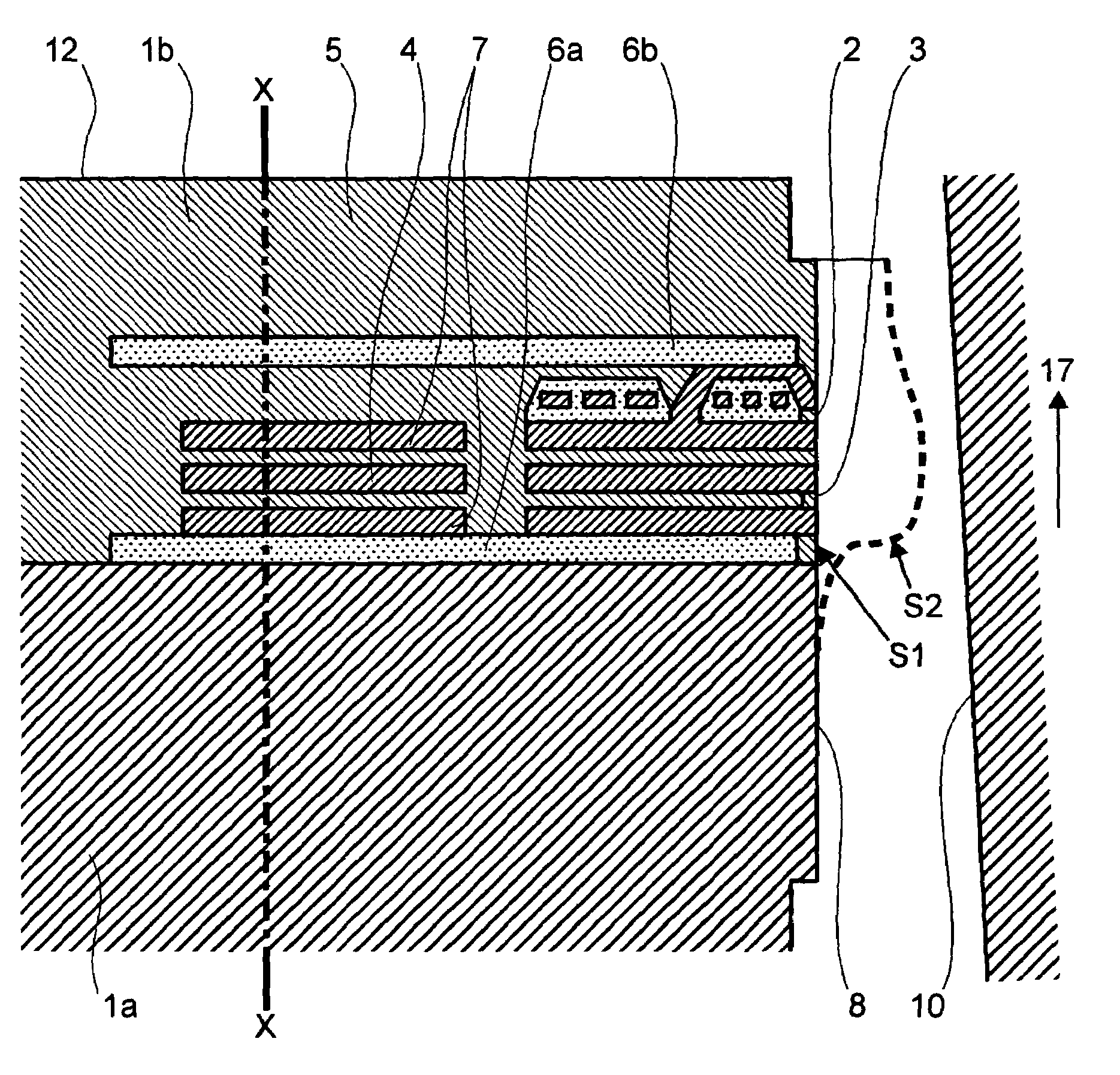
The present invention aims to reduce the heat load on the recording / reproducing device by minimizing the heat load generated by the thermal actuator. This is achieved by positioning the heating device in a way that its end portion is located deeper than the surface of the recording / reproducing element, and by enclosing the recording / reproducing element with a low rigidity film to cut off the force from the materials of circumferences against the deformation. This reduces the energy required for protruding the recording / reproducing element and reduces the heat load bearing upon it, leading to improved efficiency of converting electric power into an amount of deformation in the thermal actuator.

Problems solved by technology

For example, a reproducing element applying the magneto-resistitve effect (i.e., MR effect) therein, now being mainly used, has a problem that it is weak against the heat load, and it is shortened in the life-time thereof if being exposed for a long time under high temperature condition.
However, if the heating device is located in the vicinity of the recording / reproducing device, there is a possibility that the lifetime of the recording / reproducing element may be shortened due to the heating thereof.
In particular, for the magnetic disk to be installed in equipments being portable, there is a strict restriction in the consumption of electric power, therefore it will come up to be a big problem.

Method used


Image

  • Magnetic head slider and magnet disk apparatus
  • Magnetic head slider and magnet disk apparatus
  • Magnetic head slider and magnet disk apparatus

Examples


Embodiment Construction

[0024]Hereinafter, explanation will be given on a magnetic head slider and a magnetic disk using thereof, according to embodiments of the present invention, by referring to the drawings attached therewith.

[0025](Entire Device)

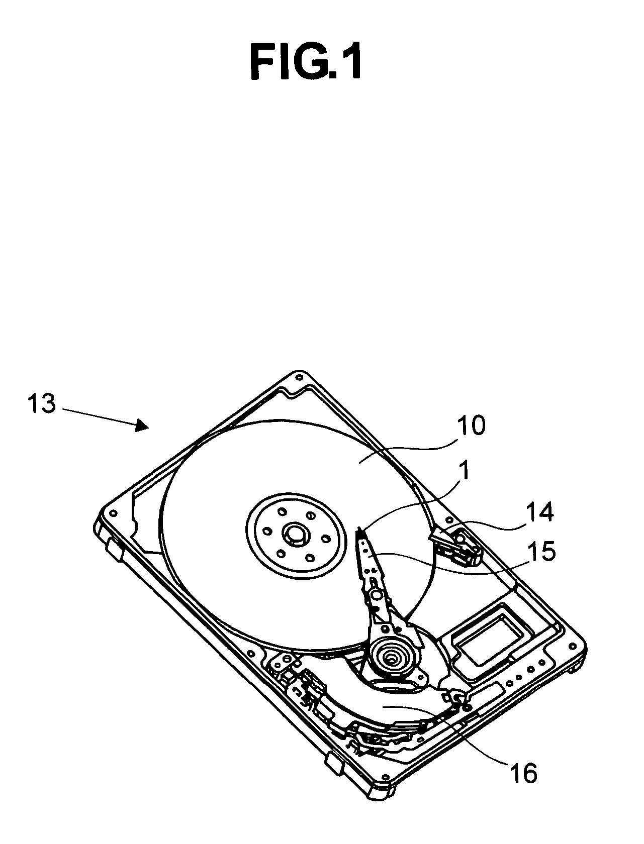
[0026]FIG. 1 shows an outline structure of the magnetic disk device, according to one embodiment of the present invention.

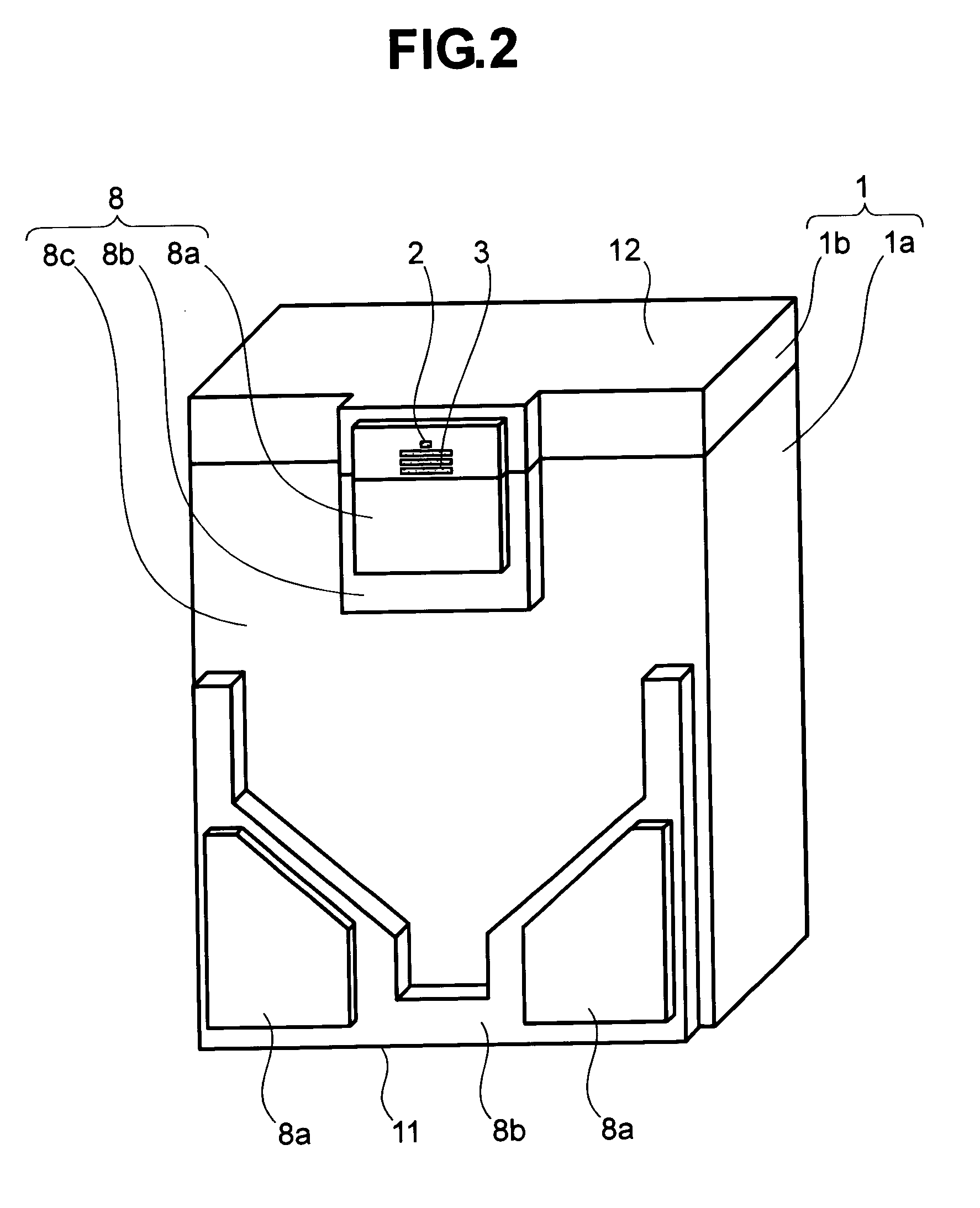
[0027]The magnetic disk device has a magnetic disk 10, storing magnetic information thereon and being rotated by a spindle motor, and a magnetic head slider (hereinafter, being simply called by a “slider”) 1, mounting a recording / reproducing element thereon and being supported and positioned in the radial direction thereof by means of a load beam 15, wherein the slider runs relatively on the magnetic disk 10, thereby reading and / or writing the magnetic information on the magnetic disk. The slider mentioned above can float thereon, due to the wedge film effect of an air as to be an air lubricated bearing, and therefore it never brings about s...


PUM

PropertyMeasurementUnit
distanceaaaaaaaaaa
distanceaaaaaaaaaa
resistanceaaaaaaaaaa

Abstract

In a slider using thermal expansion type, being adjustable on a flying height thereof, having problems to be solved, i.e., to reduce the electric power consumption, and to lesson the heat load upon a reproducing element thereof, wherein a heating device 4 is located separating from tip portions of the recording and reproducing elements 2 and 3. Also, for deforming only the vicinity of the heating device 4 and the recording and reproducing elements 2 and 3, so as to protrude from, the heating device 4 and the recording and reproducing elements 2 and 3 are surrounded by a resin film 6 of small rigidity, thereby increasing an amount of protrusion of the recording and reproducing elements 2 and 3 per a unit of electric power, but without increasing temperature of the reproducing element 3, with an aim of the structure of cutting off the force from materials of circumferences against the deformation.

Description

BACKGROUND OF THE INVENTION[0001]The present invention relates to a slider, to be applied into a magnetic disk apparatus, and has a function of adjusting a distance between the magnetic disk and a magnetic head thereof.[0002]Conventionally, for example, in Japanese Patent Laying-Open No. Hei 5-20635 (1993) is already known a magnetic head, having a thin-film magnetic head device, in which a lower portion magnetic pole, a thin-film coil being formed insulating through an insulating material layer, an upper magnetic pole, and a protection layer are formed, sequentially, on a substrate. In such the magnetic head, a thin-film resistor is formed within an inside of the layer of insulating material mentioned above, so that a tip portion of the magnetic pole can expand thermally, while conducting electricity therethrough, thereby to project or protrude it from.[0003]Among recording elements to be used for recording, or reproducing elements to be used for reproducing, or recording / reproduci...

Claims


Application Information

Patent Timeline
Patent Type & Authority Patents(United States)
IPC IPC(8): G11B5/127G11B5/31G11B5/60G11B21/21
CPCG11B5/6064G11B5/6005G11B5/607
Inventor KURITA, MASAYUKISHIRAMATSU, TOSHIYATANAKA, HIDEAKIYONEKAWA, SUNAOMIYAKE, KOJIKOHIRA, HIDEKAZUTOKUYAMA, MIKIO
Owner HITACHI GLOBAL STORAGE TECH JAPAN LTD
Learn More