Bracket assembly for lifting and supporting a foundation
a bracket assembly and foundation technology, applied in the direction of foundation engineering, building repairs, construction, etc., can solve the problems of difficult to provide a bracket assembly, piers directly below a foundation become impractical, piers with questionable flexural rigidity, etc., to reduce the induced bending moment and resist rotation and slippage
- Summary
- Abstract
- Description
- Claims
- Application Information
AI Technical Summary
Benefits of technology
Problems solved by technology
Method used
Image
Examples
second embodiment
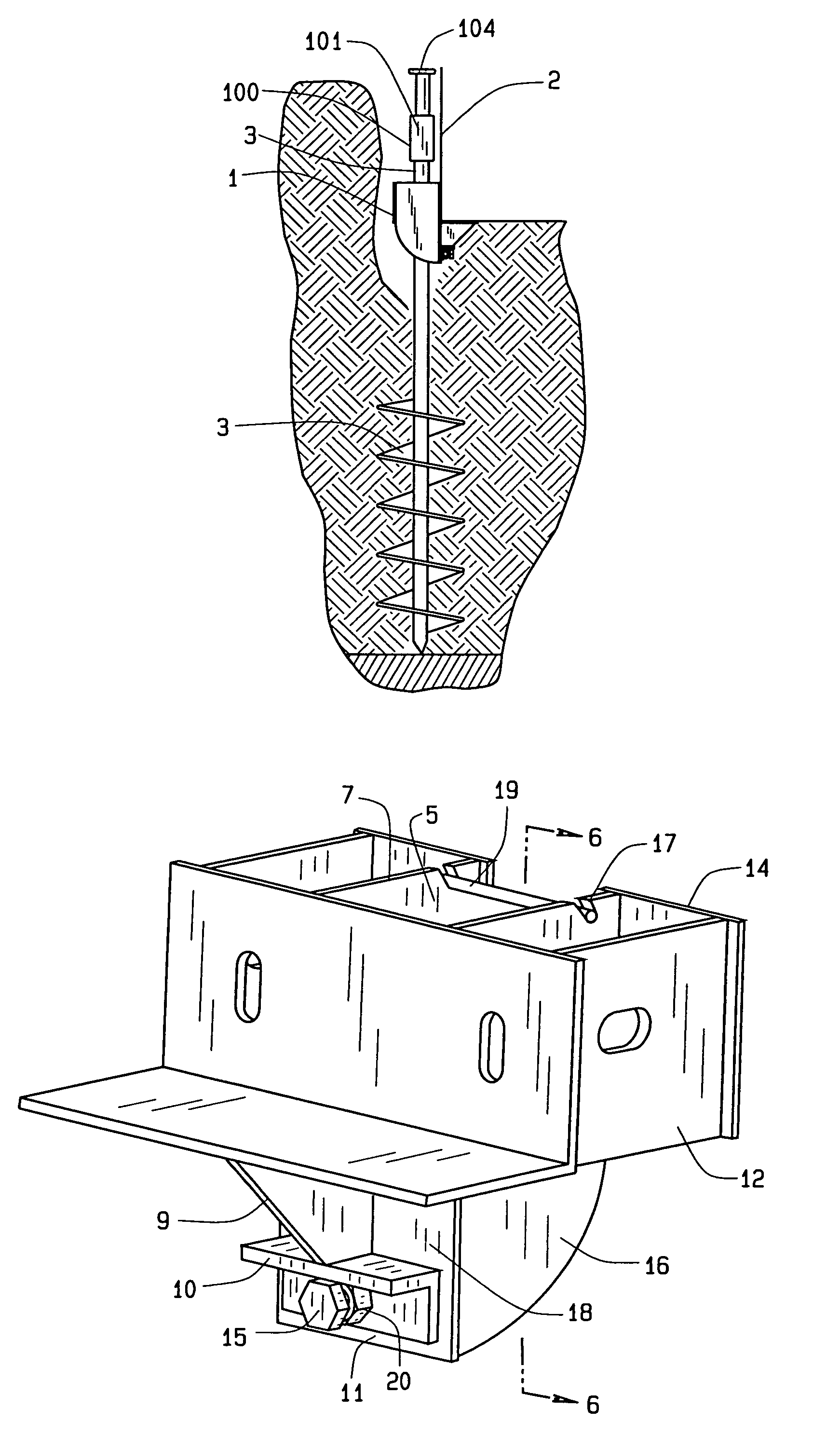
[0047]the bracket assembly 1 appears in FIG. 8. The bracket assembly 1 begins with a hollow tube 25, generally square in cross section and oriented upright. Serving as a pier guide, the tube 25 fits the shape of the top of a pier 3. Those skilled in the art will recognize that a variety of shapes can be used in addition to the square shape of the tube 25 described. A bearing angle 8 spans across the tube 25 in an L shape cross section with the vertex of the L shape generally at the center of the present invention 1. The bearing angle 8 contacts the front of the tube 25. Centered beneath the bearing angle 8, a gusset 9 hangs downwards and joins to the front of the tube 25 as well. The gusset 9 has a planar shape generally triangular and perpendicular to a leg of the bearing angle 8 and to the tube 25. Beneath the gusset 9, an angle 10 spans the width of the tube 25. As before, the gusset 9 welds or joins to the bearing angle 8, the lower plate 18, and the angle 10. The angle 10 has a...
third embodiment
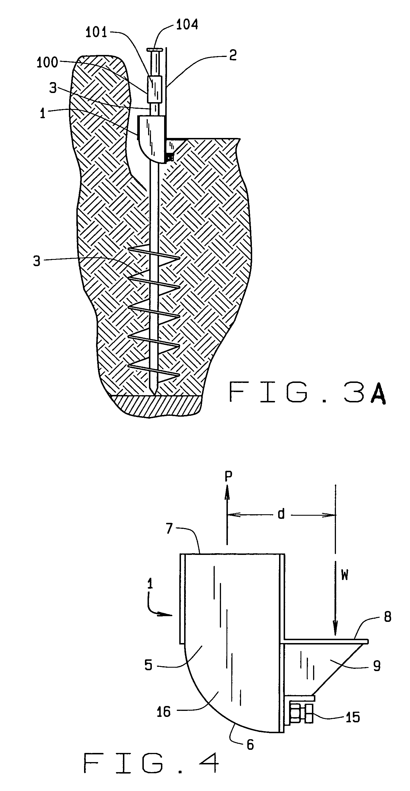
[0052]the bracket assembly 1 appears in FIG. 11. The bracket assembly 1 begins with two parallel and spaced apart plates 16. A plate 16 has a generally rectangular shape with two ends. The first end 6 has a quarter circle or arcuate shape when viewed from the side of the bracket assembly 1 and the opposite second end 7 has a horizontal or square shape denoting the top of the bracket assembly 1. A bearing angle 8 spans across the plates 16 in an L shaped cross section with the vertex of the L shape generally at the center of the present invention. Centered beneath the bearing angle 8, a gusset 9 depends to a lower plate 18. The gusset 9 has a planar shape generally triangular and parallel to the plates 16. The lower plate 18 spans between the plates 16 beneath the bearing angle 8 to the first ends 6. Beneath the gusset 9, an angle 10 spans across the lower plate 18. The gusset 9 joins by welding to the bearing angle 8, the lower plate 18, and the angle 10. The angle 10 has a generall...
fourth embodiment
[0059]the bracket assembly 1 appears in FIG. 15. The bracket assembly 1 begins with two parallel and spaced apart plates 16 as in FIG. 5. A plate 16 has a generally rectangular shape with two ends. The first end 6 has a quarter circle or arcuate shape when viewed from the side of the bracket assembly 1 and the opposite second end 7 has a horizontal or square shape denoting the top of the bracket assembly 1. A bearing angle 8 spans across the plates 16 in an L shaped cross section with the vertex of the L shape generally at the center of the present invention 1. Centered beneath the bearing angle 8, a gusset 9 depends to a lower plate 18. The gusset 9 has a planar shape generally triangular and parallel to the plates 16. The lower plate 18 spans between the plates 16 beneath the bearing angle 8 to the first ends 6. Beneath the gusset 9, a angle 10 spans the lower plate 18. The angle 10 has a generally L shaped cross section with the vertex of the L shape towards the center of the pre...
PUM
 Abstract
Description
Claims
Application Information
 - R&D
- Intellectual Property
- Life Sciences
- Materials
- Tech Scout
- Unparalleled Data Quality
- Higher Quality Content
- 60% Fewer Hallucinations
Browse by: Latest US Patents, China's latest patents, Technical Efficacy Thesaurus, Application Domain, Technology Topic, Popular Technical Reports.
© 2025 PatSnap. All rights reserved.Legal|Privacy policy|Modern Slavery Act Transparency Statement|Sitemap|About US| Contact US: help@patsnap.com


