
Connector device

a technology of connecting device and connector, which is applied in the direction of coupling device connection, two-part coupling device, electrical apparatus, etc., can solve the problems of plastic fatigue from deformation, bulky and inefficient, and failure of latching mechanism, and achieve the effect of resisting the rotation of the collar

Active Publication Date: 2015-09-15
DG INTERCONNECTS
View PDF27 Cites 2 Cited by
  • Summary
  • Abstract
  • Description
  • Claims
  • Application Information

AI Technical Summary

Benefits of technology

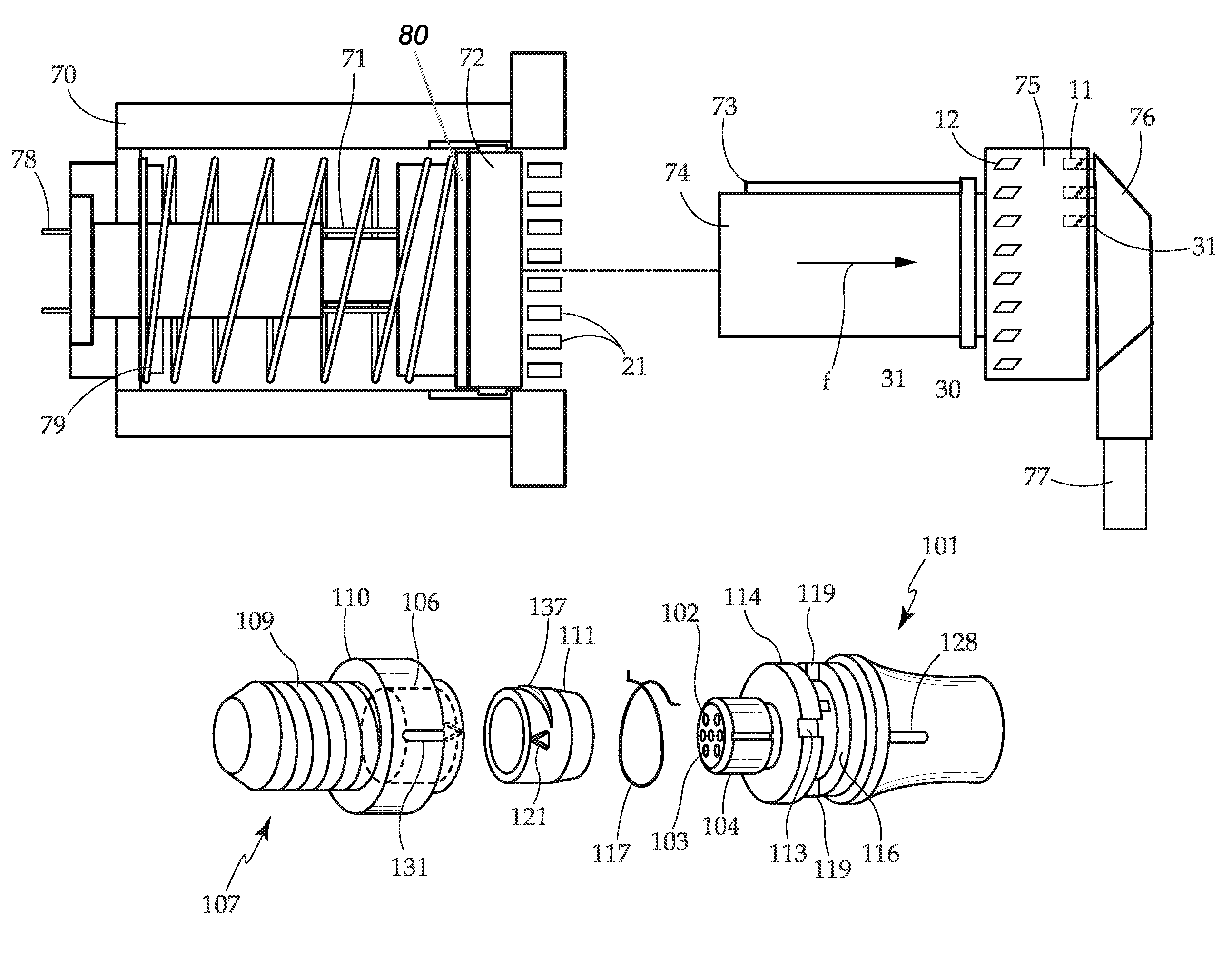
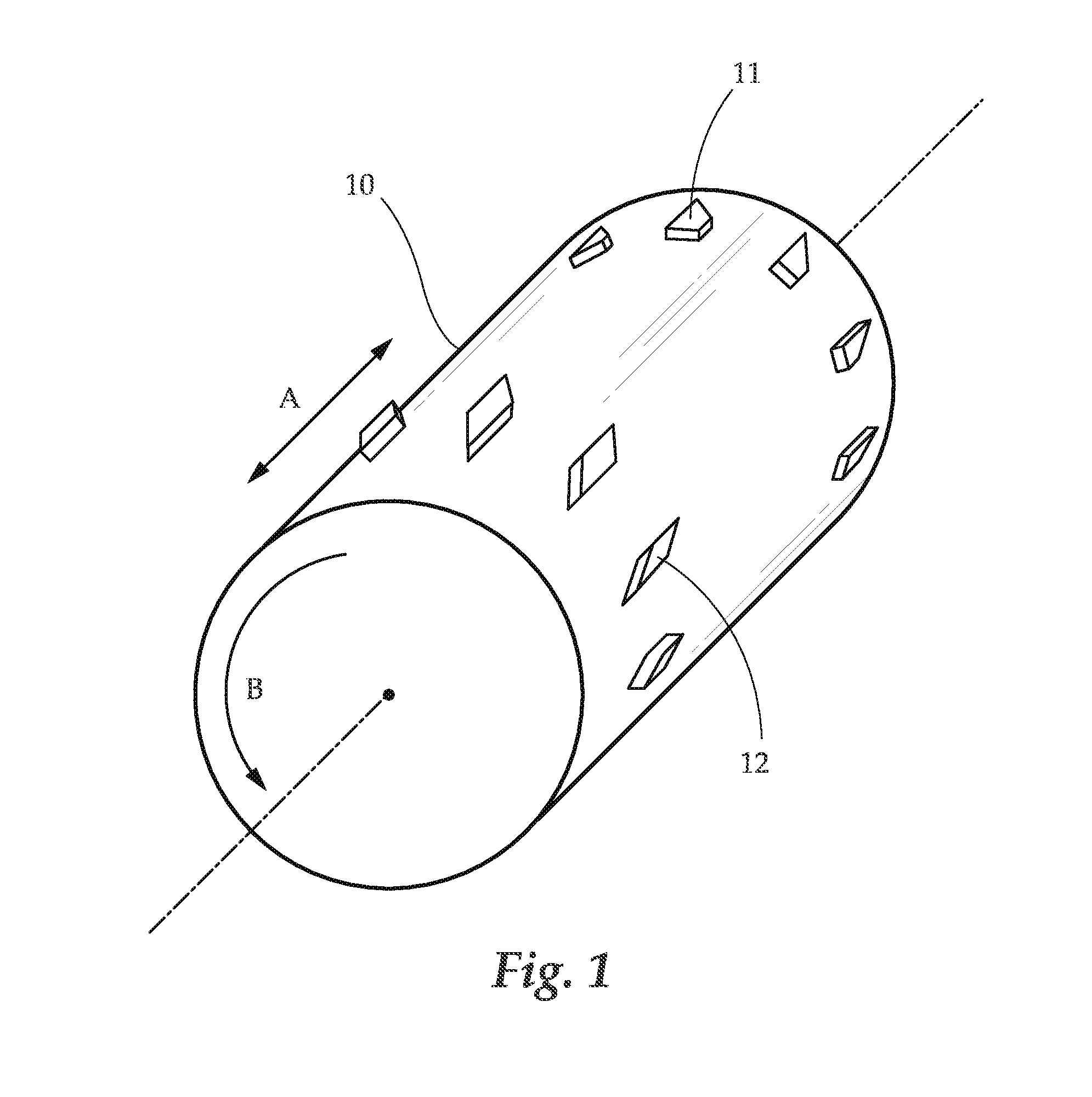
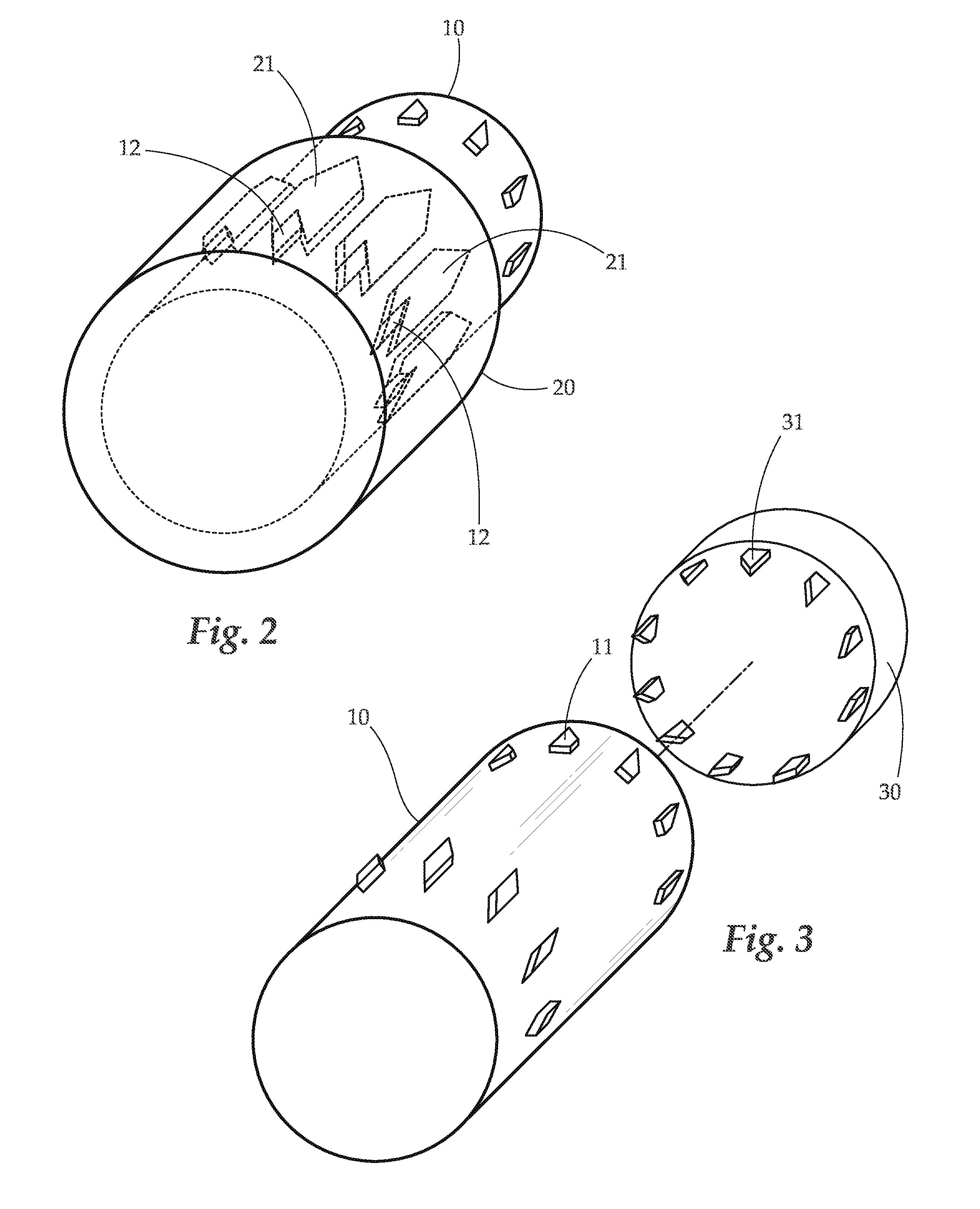
[0010]In another aspect, an electrical connector is provided. The electrical connector comprises a first and second tubular connector bodies having telescopingly engagable body portions and axial mating electrical contacts. The electronic connector further comprises an annular collar rotatably held on the first body, which is sized to fit within a cavity formed by the second body. A spring is connected to the collar, the ends of the spring being between the first body and the collar, and the spring is configured to yieldingly resist rotation of the collar. The electrical connector has at least two axially opposed tabs. A first tab is on an outer surface of the annular collar. A second tab is on an inner surface of the cavity formed by the second body. The tabs are configured with opposing flaring cam surfaces that cooperatively produce rotation of the collar relative to the second body when the bodies are telescoped to a mated contact position. Thus, the cam surfaces guide the first tab around the second tab. This electric connector is configured such that the spring yields as the collar is rotated by the cam tabs during contact mating, and then the spring can rotate the first tab to a latching position axially behind the second tab, locking the connector bodies in a mated contact position. Further, a circumferential ramp extends from an outer surface of the annular collar. The circumferential ramp is configured to be guided by the second tab upon manual axial rotation of the collar relative to the second body when the two are mated together. The guiding of the circumferential ramp by the second tab urges the collar out of the receptacle cavity, thus facilitating removal of the first body from the second body. Depending on embodiment, a spring may provide an axial force urging the plug out of the receptacle, thereby at least partially eliminating the need for the ramp.

Problems solved by technology

If such a deforming latching body is frequently engaged and disengaged the plastic fatigues from the deformation and the latching mechanism fails.
Some electrical connectors with push to connect-twist to remove (referred to herein as a push-twist connector), twist to connect / twist to remove, and push to connect-pull to remove (push-pull connector) features have been developed, however they are bulky and inefficient.

Method used


Image

  • Connector device
  • Connector device
  • Connector device

Examples


Embodiment Construction

[0027]The detailed description set forth below in connection with the appended drawings is intended as a description of presently preferred embodiments of the invention and does not represent the only forms in which the present invention may be constructed and / or utilized. The description sets forth the functions and the sequence of steps for constructing and operating the invention in connection with the illustrated embodiments.

[0028]Generally, one aspect of the present invention concerns connector, such as an electrical connector, that is engaged and disengaged by an inward pushing movement. Another aspect of the present invention concerns a connector, such as an electrical connector, that is engaged by a pushing motion and disengaged by a twisting motion. The present invention may be used for any connection, though it is particularly applicable to electrical connection of a plug to a receptacle. Particular embodiments of the connector include electronic connections to an interfac...


PUM


Abstract

Electrical connector systems and devices are provided. Included are push-push electrical connectors, as well as push-twist electrical connectors. These electrical connectors are configured to be user friendly, space efficient, and safe.

Description

BACKGROUND OF THE INVENTION[0001]1. Field of the Invention[0002]The present invention relates generally to a connector device. More particularly, the present invention relates to a push-on / push-off connector allowing the connector to be secured and removed by a pushing motion.[0003]2. Description of Related Art[0004]With telescopically mating electrical connectors such as a plug and a socket it is often desirable or necessary to lock the two connector bodies together after their conductive contacts have been physically and electrically joined. Single conductor connectors with some form of bayonet joint may be rotated to a locking position. Multiple male and female contacts, however, must be slidingly joined telescopically without rotation, and typically have used a pliable plastic connector body which is deformed as a catch on one connector body rides over a detent on the other connector body to a locking position beyond the detent. If such a deforming latching body is frequently en...

Claims


Application Information

Patent Timeline
Patent Type & Authority Patents(United States)
IPC IPC(8): H01R13/213H01R24/66H01R13/625
CPCH01R13/625H01R24/66H01R13/622H01R13/62905H01R13/6456
Inventor BEHNING, CHRISTIAN
Owner DG INTERCONNECTS
Learn More