
Method and apparatus for driving LED light sources for a projection display

a technology of led light sources and projection displays, applied in the direction of picture reproducers using projection devices, semiconductor lasers, instruments, etc., can solve the problems of difficult to achieve suitable projection image brightness, high cost and error prone, and often less than satisfactory optical performance of conventional projectors, so as to achieve the effect of not reducing the brightness of the light sour

Inactive Publication Date: 2006-08-08
SEIKO EPSON CORP
View PDF33 Cites 108 Cited by
  • Summary
  • Abstract
  • Description
  • Claims
  • Application Information

AI Technical Summary

Benefits of technology

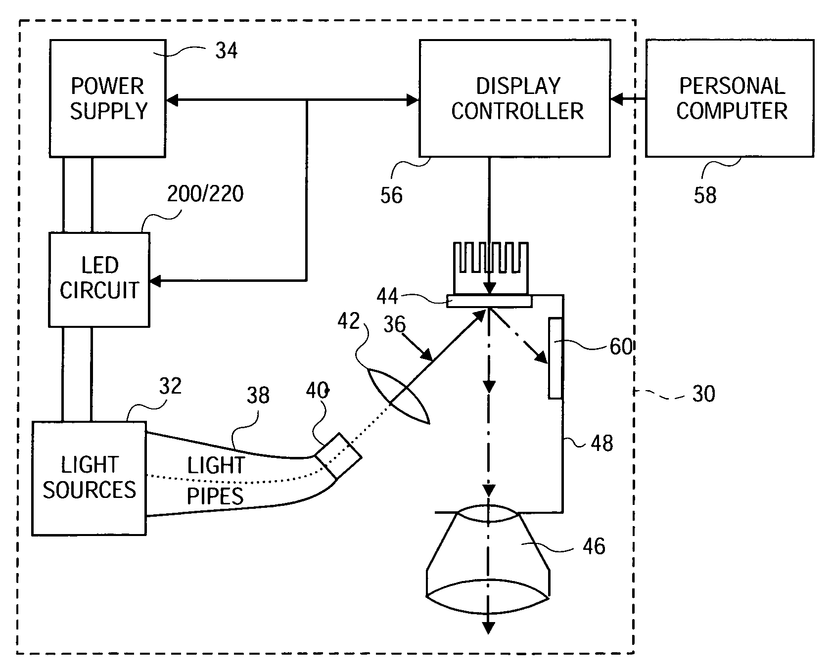
[0013]According to one aspect of the invention, a circuit is provided to drive LEDs that emit light in desired wavelengths, such as the primary colors red, green, and blue, which serve as the light source for a projection display system. The LED circuit contains one or more series-parallel arrays of each color LED, also referred to as a color channel. A display controller synchronizes the color output of each color channel with image data received from an image data source such as a personal computer. The synchronization is achieved by electronically adjusting the current path, current source and / or current level through the color channels without reducing the brightness of the light source. Redundant LEDs and / or color channels are provided to accommodate further adjustments to the current path, source and / or level to compensate for the failure of one or more LEDs or color channels.

Problems solved by technology

However, the optical performance of conventional projectors is often less than satisfactory.
For example, suitable projected image brightness is difficult to achieve, especially when using compact portable color projectors in a well-lighted room.
Because LCD displays have significant light attenuation and triple path color light paths are heavy and bulky, portable multimedia projectors typically employ DMD displays in a single light path configuration.
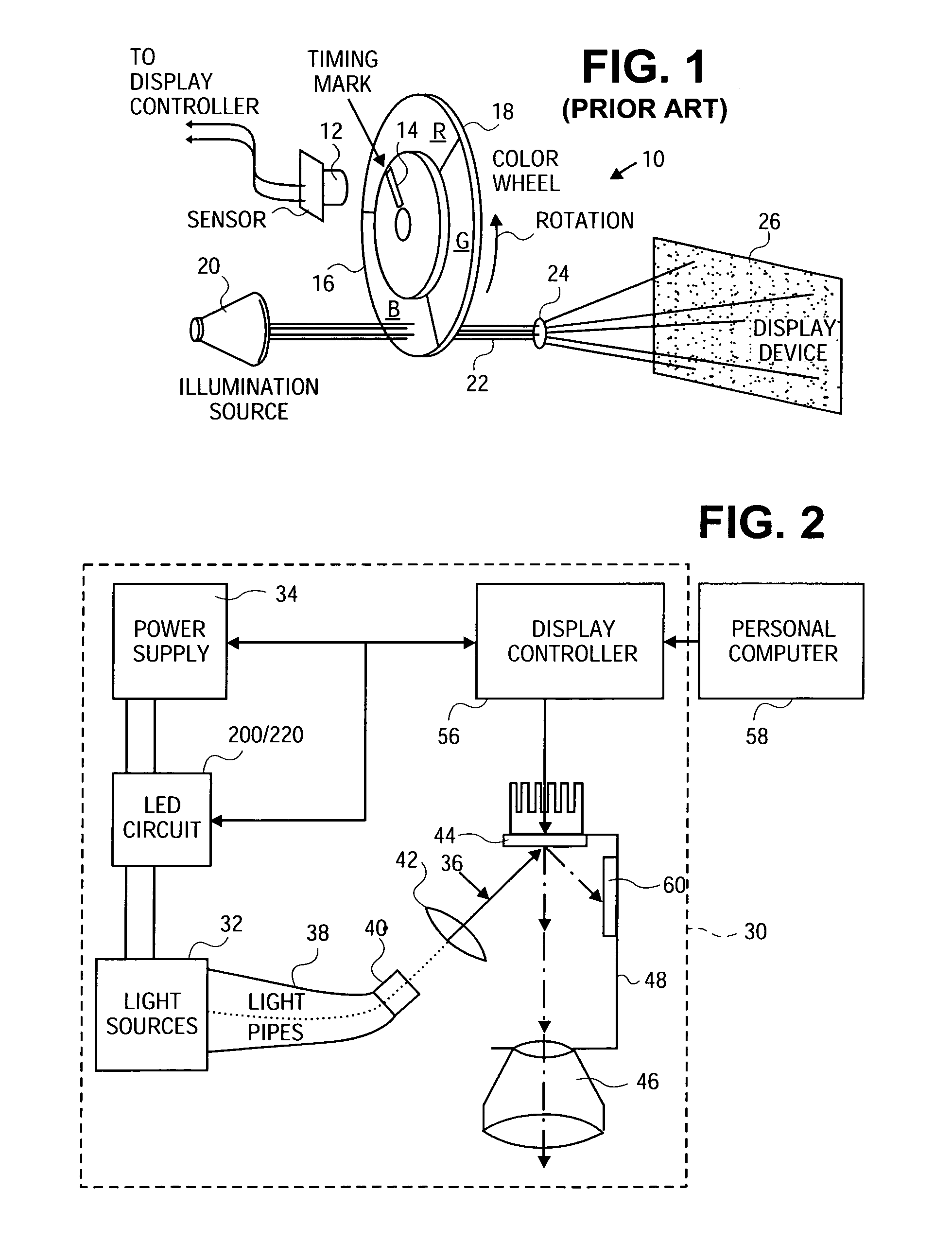
This alignment is typically a costly and error prone mechanical adjustment that accounts for angular differences between motor 16 and the mechanical mounting of filter segments R, G, and B. Of course, electrical or mechanical delays associated with sensor 12 further contribute to alignment errors.
Unfortunately, the timing duty cycle reduces the total amount of illumination available for displaying each color which, in turn, reduces the brightness of the displayed color image.
In addition, color wheels 18 and their associated motors are heavy and noisy.
However, LED array circuits in traffic signals, which display simple static images, do not address the complex sequencing and control requirements for the generation of light suitable for a projection display system.

Method used


Image

  • Method and apparatus for driving LED light sources for a projection display
  • Method and apparatus for driving LED light sources for a projection display
  • Method and apparatus for driving LED light sources for a projection display

Examples


Embodiment Construction

[0026]FIG. 2 shows a single path embodiment of a multimedia projector 30 of the present invention that employs multiple, relatively monochromatic light sources 32 of two or more different wavelengths. Light sources 32 are light emitting devices (LEDs) or LED arrays and are driven by an LED circuit 200 powered by a power supply 34. The LEDs are preferably light emitting diodes or laser diodes, but can be any device capable of emitting light when driven by an LED circuit 200. Light emitted from light source 32 generally propagates along separate and common portions of an optical path 36 that may include light transmission guides 38, an optical integrator 40, one or more optical path lenses 42, a display device 44, a projection lens group 46 and various other optical components known to skilled persons.

[0027]Display device 44 is preferably a digital micro-mirror device (DMD) but may alternatively be a reflective liquid crystal on semiconductor (LCOS) array device or an LCD light valve....


PUM


Abstract

A circuit is provided to drive LEDs or diode lasers that emit light in desired wavelengths, such as the primary colors red, green, and blue, which serve as the light source for a projection display system. A display controller controls one or more series-parallel arrays of each color LED in the LED circuit with control signals to synchronize the color output of the light source with image data received from an image data source such as a personal computer. Synchronization is achieved by sending control signals to the power supply and circuit switches to sequence the color output in a single path system or adjust continuous color output in a triple path system with minimal or no reductions in the brightness of the projected image.

Description

BACKGROUND OF THE INVENTION[0001]1. Field of the Invention[0002]This invention relates to image projection displays and more particularly to the circuitry to drive an LED light source employed in an optical pathway of such displays.[0003]2. Background Information[0004]Projection systems have been used for many years to project motion pictures and still photographs onto screens for viewing. More recently, presentations using multimedia projection systems have become popular for conducting sales demonstrations, business meetings and classroom instruction. In a typical operating mode, multimedia projection systems receive analog video signals from a personal computer (“PC”). The video signals may represent still, partial, or full-motion display images of a type rendered by the PC. The analog video signals are typically converted in the projection system into digital video signals, and the signals are electronically conditioned and processed to control an image-forming device, such as a...

Claims


Application Information

Patent Timeline
IPC IPC(8): G09G3/32G02F1/13G02F1/133G09G3/20G09G3/34G09G3/36H01L33/00H01L33/08H01S5/062H04N9/31H05B37/02
CPCG09G3/3406H04N9/3197H04N9/3155H04N9/3164G09G2310/0235G09G2320/0626
Inventor PARKER, FREDERICK S.
Owner SEIKO EPSON CORP
Learn More