Power supply control device for an image forming apparatus

Inactive Publication Date: 2006-08-08
RICOH KK
View PDF11 Cites 7 Cited by
  • Summary
  • Abstract
  • Description
  • Claims
  • Application Information

AI Technical Summary

Benefits of technology

[0007]It is an object of the present invention to provide a simple, stably operable power supply control device capable of obviating unusual occurrences ascribable to the unexpected turn-off of a power supply, and an image forming apparatus including the same.
[0009]Also, in accordance with the present invention, a power supply control device for an image forming apparatus includes a power switch including an AC opening / closing circuit assigned to an input AC voltage and at least one signal opening / closing circuit assigned to a signal. A DC power supply converts the AC voltage input via the AC opening / closing circuit to a DC voltage for drive and a DC voltage for control and applies the DC voltages to the image forming apparatus. A shutoff detector detects the state of the signal opening / closing circuit to thereby detect the turn-off of the power switch. A shutoff processing section executes processing, which avoids an error of the image forming apparatus and protects a memory, during an interval between the input of a signal output from the shutoff detector and representative of the shut-off of the power switch and the drop of a DC voltage output to a preselected level.

Problems solved by technology

This gives rise to the following problems.
Further, in an advanced image forming apparatus with a server function implemented by a hard disk, when the power switch of the apparatus is turned off during writing of data in the hard disk or during access to the hard disk, it is likely that data stored in the hard disk are destroyed.
Moreover, assume that the power switch is turned off while, e.g., a motor is in rotation, causing the control system stop operating due to voltage drop before the voltage drop of the drive system.
Then, it is likely that mechanical arrangements are damaged due to unusual rotation of the motor.
This kind of scheme, however, is apt to fail to shutoff power supply in the event of emergency, e.g., when a CPU runs away or when a heater included in a fixing unit malfunctions.

Method used


Image

  • Power supply control device for an image forming apparatus
  • Power supply control device for an image forming apparatus
  • Power supply control device for an image forming apparatus

Examples


Embodiment Construction

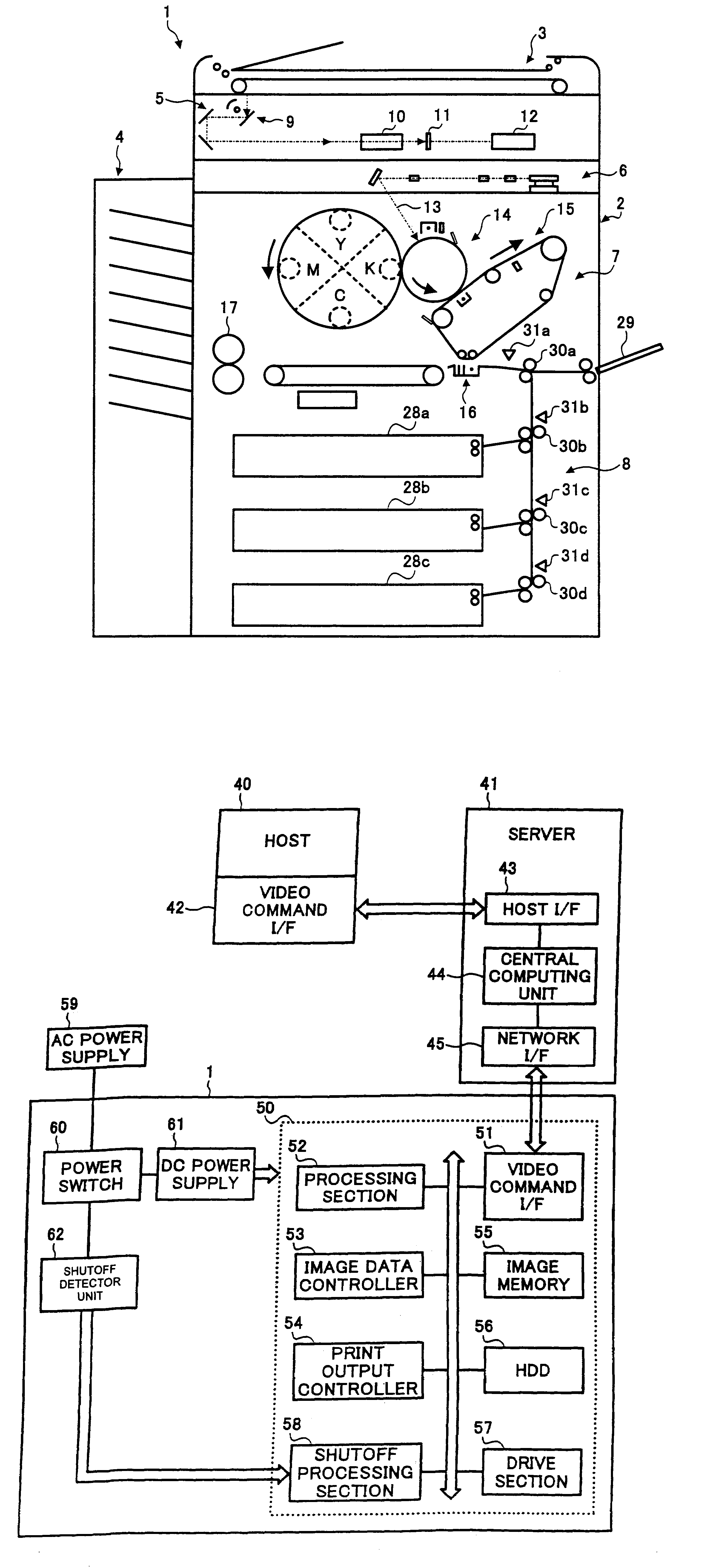
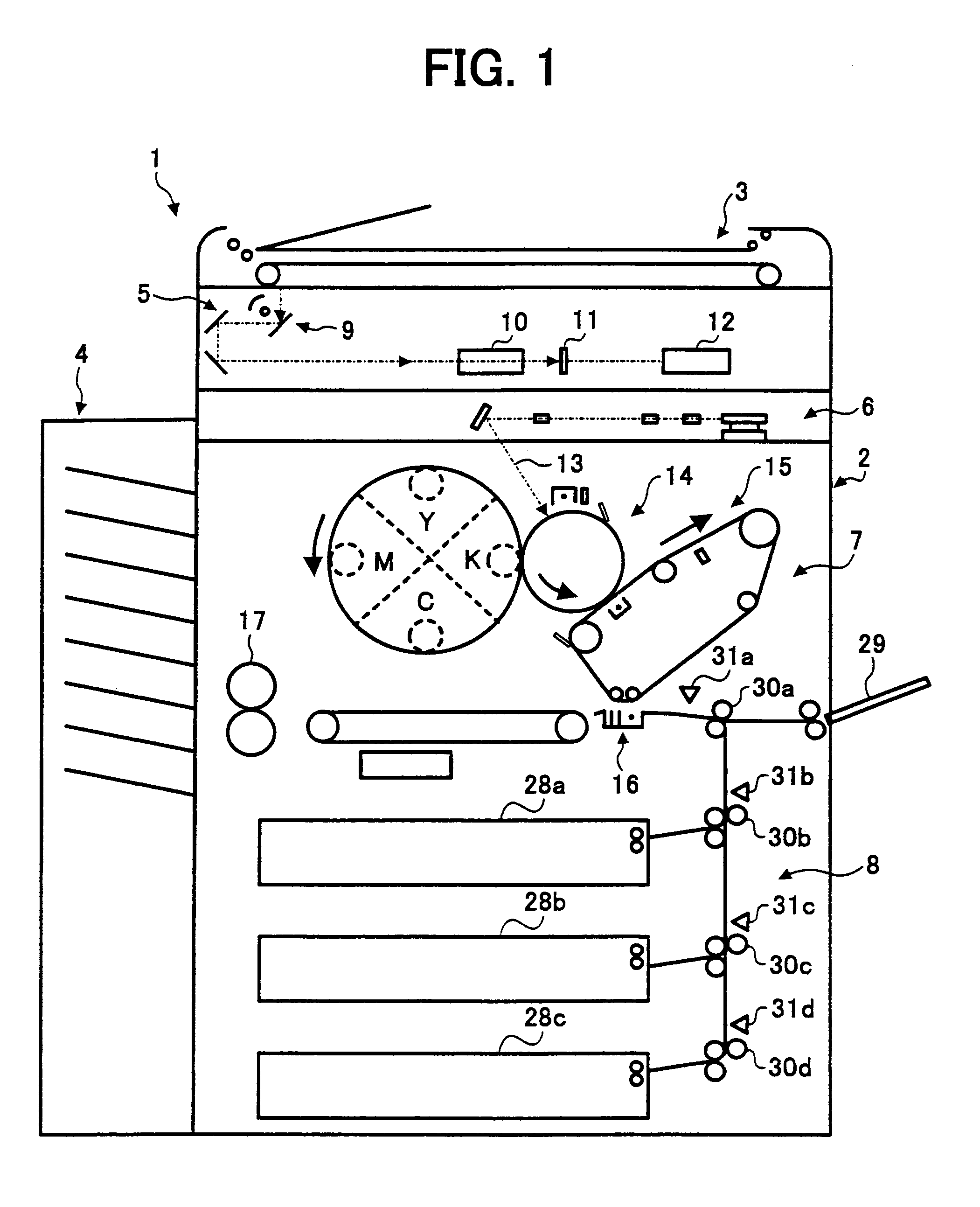
[0018]Referring to FIG. 1 of the drawings, an image forming apparatus embodying the present invention is shown and implemented as a color copier by way of example. As shown, the color printer, generally 1, is made up of a copier body 2, an ADF (Automatic Document Feeder) 3, and a sorter 4.

[0019]The copier body 2 includes a scanning unit 5, a writing unit 6, an engine 7, and a sheet feeding unit 8. The scanning unit 5 includes a carriage 9 loaded with a plurality of mirrors 9, a lens 10, a CCD (Charge Coupled Device) image sensor 11, and a buffer 12. The scanning unit 5 scans a document fed from the ADF 3 to thereby read the image of the document. The writing unit 6 includes a laser or light source and a polygonal mirror and emits a laser beam 13 modulated in accordance with image data representative of the document image toward the engine 7.

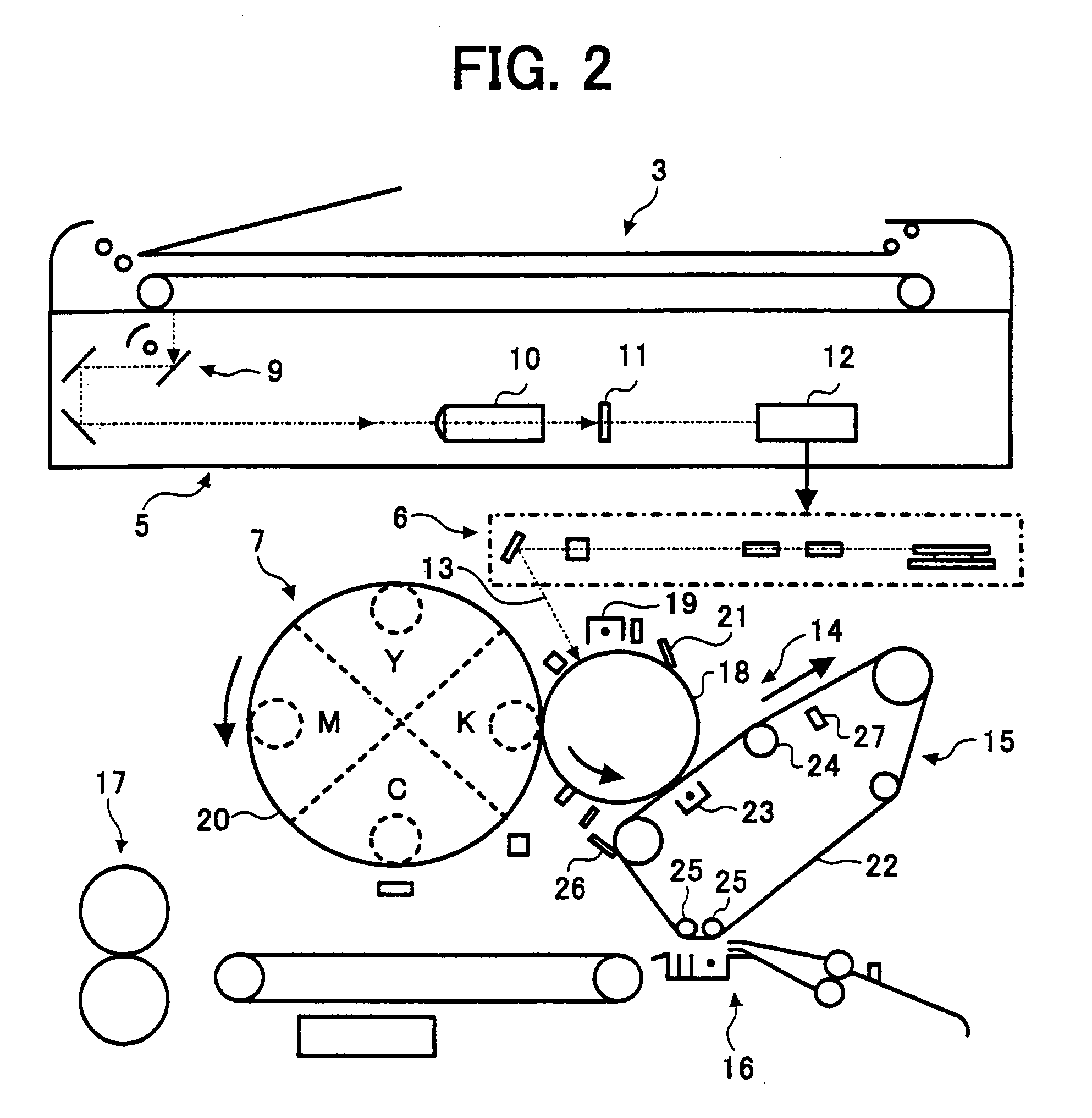
[0020]As shown in FIG. 2, the engine 7 includes an image forming unit 14, a primary image transferring unit 15, a secondary image transferring u...


PUM


Abstract

A power supply control device for an image forming apparatus of the present invention includes a shutoff detector for monitoring the state of a power switch. In response to the output signal of the shutoff detector representative of the turn-off of the power switch, a shutoff processing section executes processing for avoiding accidental error detection and protecting a memory before the output voltage of a DC power supply drops to a preselected level.

Description

BACKGROUND OF THE INVENTION[0001]1. Field of the Invention[0002]The present invention relates to a power supply control device for a copier, printer, facsimile apparatus or similar image forming apparatus and more particularly to a power supply control device capable of obviating accidental error detection when the power switch of an image forming apparatus is turned off.[0003]2. Description of the Background Art[0004]Generally, when a power switch provided on an image forming apparatus is turned off, power supply to the entire system of the apparatus including controllers is shut off. Therefore, when the operator of the apparatus inadvertently turns off the power switch, a control unit including a CPU (Central Processing Unit) automatically stops executing control without recognizing the inadvertent turn-off of the power switch. This gives rise to the following problems.[0005]When the power switch is turned off while, e.g., printing is under way, the entire drive system and entire ...

Claims


Application Information

Patent Timeline
IPC IPC(8): H01H3/02B41J29/38G03G15/00G03G21/00G05F1/10G06F1/28H04N1/00H04N1/32
CPCG03G15/5004H04N1/00885H04N1/32683H04N1/00912H04N1/00896H04N1/32358
Inventor MOTEGI, AKIHIKO
Owner RICOH KK
Why Eureka
Try Eureka