An internal high pressure forming system for pipe fittings
What is Al technical title?
Al technical title is built by PatSnap Al team. It summarizes the technical point description of the patent document.
A technology for internal high pressure forming and pipe fittings, applied in the field of high pressure forming systems for pipe fittings, can solve the problems of low quality and precision of pipe fittings, high equipment pressure holding requirements, easy deformation of molds, etc., and achieves improved quality, high fatigue strength, and thinning. volume reduction effect
Active Publication Date: 2017-01-25
CHINA NAT HEAVY MACHINERY RES INSTCO
View PDF5 Cites 0 Cited by
Summary
Abstract
Description
Claims
Application Information
AI Technical Summary
This helps you quickly interpret patents by identifying the three key elements:
Problems solved by technology
Method used
Benefits of technology
Problems solved by technology
Usually, the opening and closing and clamping force of the mold are realized by the same oil cylinder, which results in high pressure maintenance requirements for the equipment, especially for the forming of large-diameter pipe fittings. Due to the large opening and closing stroke of the mold, and the clamping force required for mold clamping is as high as Tens of thousands of tons, resulting in a large scale of the oil cylinder, especially for large-caliber internal high-pressure formed parts, the filling time is long, and the clamping force of the device at the initial stage of forming is relatively small, while the clamping force of the traditional forming device is always unique throughout the process, and It is very large, causing unnecessary waste of resources. At the same time, the clamping force directly acts on the mold during the forming process, and the mold is prone to deformation, resulting in low quality and precision of the pipe fittings and short mold life.
Method used
Image
Click on the blue label to locate the original text in one second.
Reading with bidirectional positioning of images and text.
Examples
Embodiment Construction
[0014] The structural principle and working principle of the present invention will be further described in detail below in conjunction with the accompanying drawings.
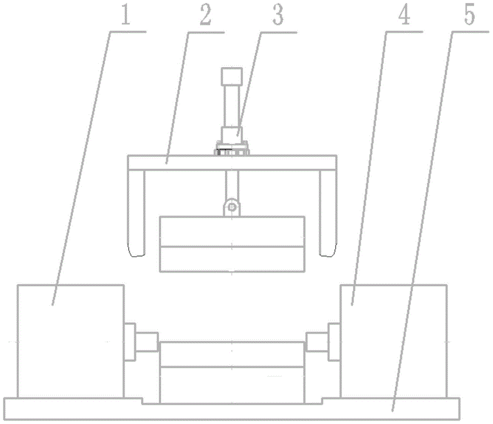
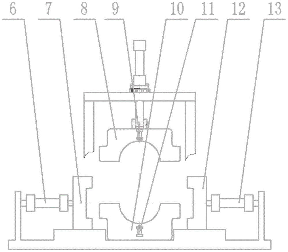
[0015] refer to figure 1 and figure 2 , a high-pressure forming system for pipe fittings, including a frame 2 and a lower platform 5, characterized in that the frame 2 is fixed on the lower platform 5, the lifting cylinder 3 is fixed on the frame 2, and is connected with the upper mold 8, because The function of the lifting cylinder 3 is to lift the upper mold 8, and its force only needs to overcome the dead weight of the upper mold 8, so the quality and type of the lifting cylinder 3 are relatively small; The oil cylinder 9 is used to separate the formed part from the upper mold 8 after forming, so as to prevent the formed pipe from being dropped and damaged when the upper mold 8 is lifted due to the deformation of the tube blank and the close fit of the upper mold 8 during the forming process. The locking...
PUM
Abstract
An intra-pipe high pressure forming system comprises a left liquid charger, a frame, a lift cylinder, a right liquid charger, a lower platform, a front lock clamp cylinder, a front lock clamp, an upper die, an upper stripping cylinder, a lower die, a lower stripping cylinder, a rear lock clamp, a rear lock clamp cylinder and the like. During hydraulic expansion, the front lock clamp and the rear lock clamp can self-lock with contact faces of the upper and lower dies and can tightly contact the dies with no need for actuating lock clamps; with increase of forming pressure, the lock clamps can counteract great forming force, produced by a pipe upon the dies and borne by the lock clamps, through self-elastic deformation; the lock clamps have low elastic deformation, which is ignorable in relation to the elastic deformation of the dies; thus, the upper and lower dies never separate during the forming process, and pipe forming quality is guaranteed. During the whole process, large cylinders for locking are not required, and tonnage and energy consumption of the system is greatly decreased; the system has the advantages such as simple structure, low manufacturing cost, good stability, convenience of control and long die life.
Description
technical field [0001] The invention belongs to the field of internal high pressure forming equipment, in particular to an internal high pressure forming system for pipe fittings. Background technique [0002] At present, with the increasing demand for mechanism integration and light weight in aviation, aerospace, automobile and machinery industries, internal high pressure forming technology has been widely used, and has gradually become a method for manufacturing complex special-shaped cross-section light-body components in industrial production. An advanced forming technology. The inner high pressure forming of pipe fittings is to fill the mold cavity with a certain pressure of forming medium after the upper and lower molds are closed. Cavity, under the joint action of high-pressure forming medium and push head feeding, the tube blank is deformed and fits the mold, so as to realize the forming of pipe fittings, such as tee and cross, etc. [0003] The tube blank is mainl...
Claims
Application Information
Patent Timeline
Application Date:The date an application was filed.
Publication Date:The date a patent or application was officially published.
First Publication Date:The earliest publication date of a patent with the same application number.
Issue Date:Publication date of the patent grant document.
PCT Entry Date:The Entry date of PCT National Phase.
Estimated Expiry Date:The statutory expiry date of a patent right according to the Patent Law, and it is the longest term of protection that the patent right can achieve without the termination of the patent right due to other reasons(Term extension factor has been taken into account ).
Invalid Date:Actual expiry date is based on effective date or publication date of legal transaction data of invalid patent.