
Optical fiber and method of measuring coefficient of kinetic friction of optical fiber

a technology of optical fiber and kinetic friction, which is applied in the direction of glass optical fibre, cladded optical fibre, instruments, etc., can solve the problems of insufficient solution, limited tensile speed of moving the sled to a certain value, and weight of the sled, etc., and achieves low occurrence rate, high reliability, and stable performance.

Inactive Publication Date: 2006-08-01
FURUKAWA ELECTRIC CO LTD
View PDF6 Cites 15 Cited by
  • Summary
  • Abstract
  • Description
  • Claims
  • Application Information

AI Technical Summary

Benefits of technology

[0022]The present invention aims to solve the above-mentioned problem, and to offer a method of measuring the coefficient of kinetic friction of optical fiber where the variations are small and reliability is high and an optical fiber with a low rate of occurrence of the discontinuity using the above-mentioned method measuring the coefficient of kinetic friction. The workload in the rewind process can be reduced by this invention.

Problems solved by technology

Up to now, for the decrease of the rate of occurrence of the discontinuity, the improvement of the tack of surface of optical fiber and the decrease of the coefficient of kinetic friction etc. are tried but an sufficient solution has not been performed.
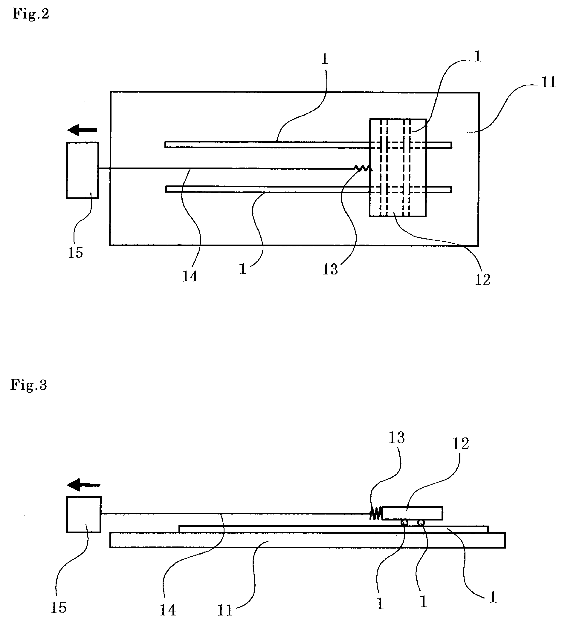
And, when the sled is loaded, the weight of the sled and the tensile speed of moving the sled are limited to a certain value.

Method used


Image

  • Optical fiber and method of measuring coefficient of kinetic friction of optical fiber
  • Optical fiber and method of measuring coefficient of kinetic friction of optical fiber
  • Optical fiber and method of measuring coefficient of kinetic friction of optical fiber

Examples


example

[0086]First of all, the following UV resins 1–10 were made as the resin of coating layers. That is, the above-mentioned radical polymerizable oligomer (I) was reacted, under the existence of a reactive monomer and a polymerization initiator, with or without the addition of surface improver, and UV resins 1–10 were prepared, as shown in the following table 1.

[0087]The Young's modulus of the resin after curing was measured on a 0.2 mm thickness film formed by curing the resin in the atmosphere under the condition of UV illuminant of 200 mW / cm2 and UV dose of 1000 mJ / cm2, by tensile test under the condition of 23° C. and tensile rate of 1 mm / min, and was calculated from the tensile strength at 2.5% distortion.

[0088]

TABLE 1UV coatings12345678910componentradicalI-155(weughtpolymerizableI-2454545ratio)oligomerI-34040I-41515I-545I-6656565reactiveII-115monomerII-220252525101010II-3816II-41010101010II-51818181515II-688II-725II-8303030polymerizationIII-121.51.51.51.51.5initiatorIII-20.50.50.5...


PUM

PropertyMeasurementUnit
Forceaaaaaaaaaa
Forceaaaaaaaaaa
Pressureaaaaaaaaaa

Abstract

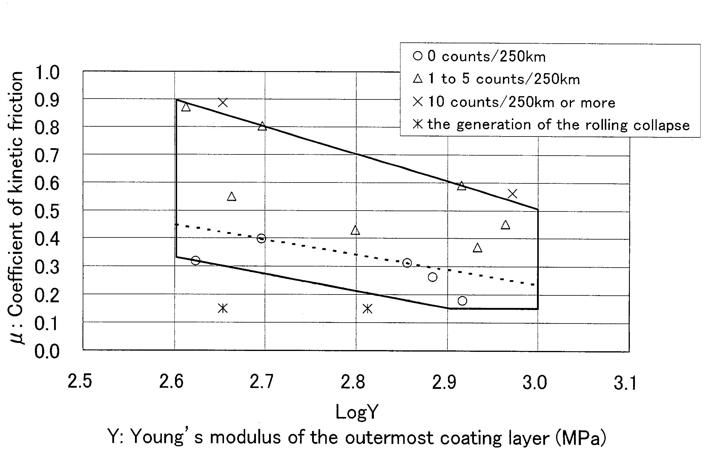
An optical fiber of the present invention comprising a bare optical fiber and one or plural coating layers on the bare optical fiber, wherein Y, the Young's modulus of the outermost coating layer is in the range of 400 to 1000 and μ, a coefficient of kinetic friction which occurs between the outermost coating layers is equal to or larger than 0.15, and further satisfying the following formulas (a) and (b);μ≦−0.9822 Log Y+3.45156   (a)μ≧−0.5418 Log Y+1.74128,   (b)wherein the unit of Y is MPa.By the present invention, optical fibers with a low rate of occurrences of the attenuation discontinuity in a measurement result by OTDR and the method of measuring the coefficient of kinetic friction of optical fiber with high reliability are offered.

Description

FIELD OF THE INVENTION[0001]This invention concerns with an optical fiber with a low rate of occurrence of the attenuation discontinuity in a measurement result by OTDR (Optical Time Domain Reflectometer) and a method of measuring the coefficient of kinetic friction of the optical fiber with high reliability.BACKGROUND OF THE INVENTION[0002]In general, the structure of optical fiber consists of two coating layers of resin composition on the surface of a bare optical fiber.[0003]Usually, a flexible coating material, called a soft material, is used to form the first coating layer and a high rigid coating material, called a hard material, is used to form the second coating layer.[0004]The ultraviolet curable resin (hereafter, the UV resin), of which the principal ingredient is the oligomer of the urethane acrylate or / and the epoxy acrylate, is adopted as the resin composition of the coating layer from the viewpoint of the curing rate.[0005]An optical fiber is manufactured by coating su...

Claims


Application Information

Patent Timeline
IPC IPC(8): G02B6/00G02B6/44C03C25/10G02B6/02G02B6/14
CPCG02B6/02395
Inventor ONO, TAKAYOSHIMOCHIZUKI, KOJI
Owner FURUKAWA ELECTRIC CO LTD
Learn More