
Method for manufacturing spark plug and apparatus for manufacturing spark plug

a manufacturing method and technology for spark plugs, applied in the manufacture of spark plugs, electric discharge tubes/lamps, electrode systems, etc., can solve the problems of impaired separation resistance of a formed spark portion, failure to form a sound weld metal portion, and inability to form a noble metal chip. , to achieve the effect of enhancing the weld strength and service life of the spark portion

Inactive Publication Date: 2006-08-01
NGK SPARK PLUG CO LTD
View PDF12 Cites 10 Cited by
  • Summary
  • Abstract
  • Description
  • Claims
  • Application Information

AI Technical Summary

Benefits of technology

[0007]It is therefore an object of the invention to provide a method and an apparatus for manufacturing a spark plug which avoid depth insufficiency of the weld metal portion and thickness insufficiency of the spark portion, and which thus enhances the weld strength and service life of the spark portion.
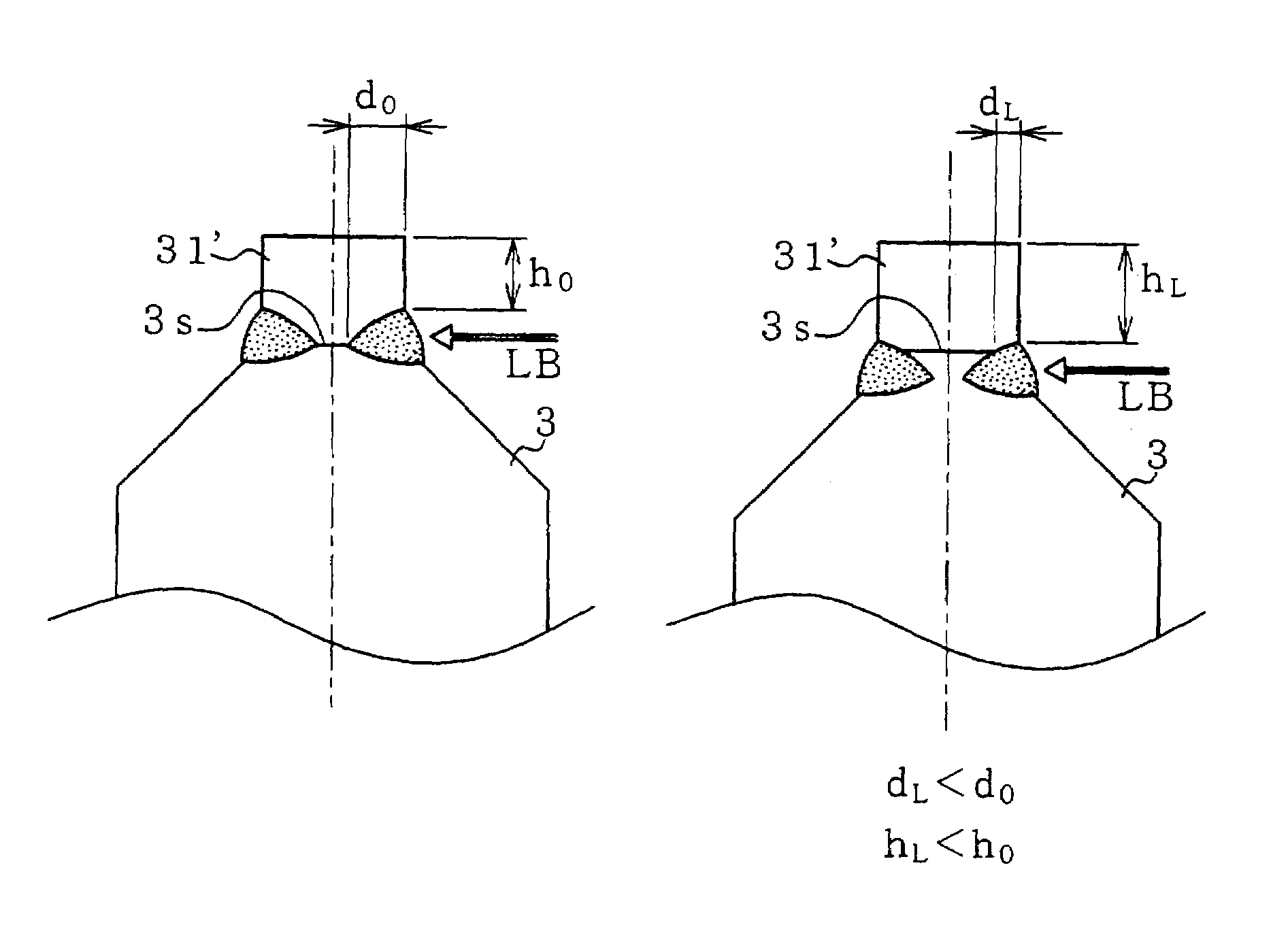
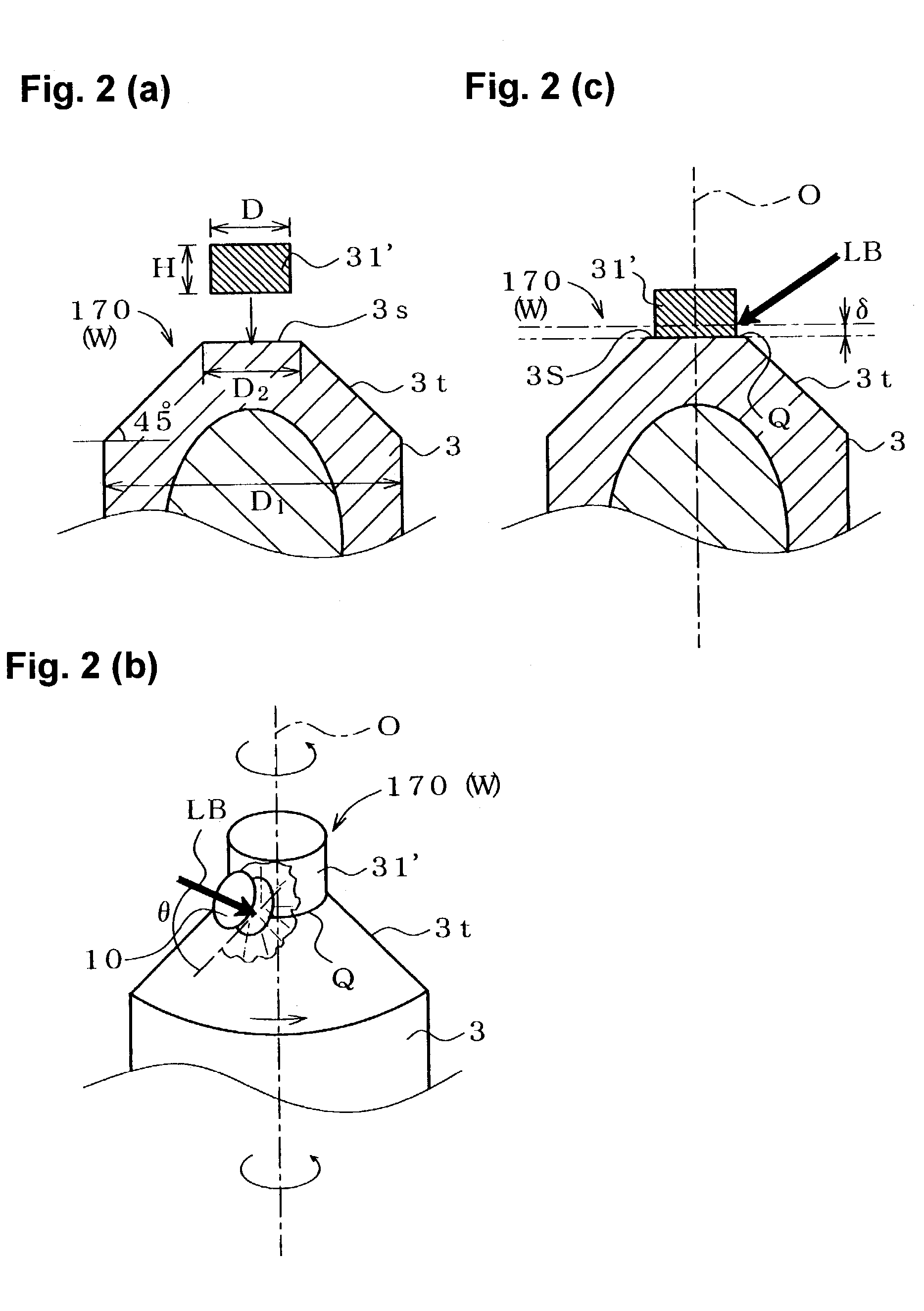
[0015]The inventors have carried out extensive studies, and as a result have found that, when laser beam welding is employed for forming a full-circled weld metal portion that joins a noble metal chip to a center electrode, a variation in the position of irradiation with a laser beam causes the depth insufficiency of a weld metal portion or the thickness insufficiency of a spark portion. After carrying out further studies, the inventors found that control of the position of irradiation with a laser beam relative to the chip joint face as viewed along the axial direction of the center electrode is effective for solving the above-mentioned problems. Specifically, the position of the chip joint face of the center electrode as viewed along the axial direction of the center electrode is detected, and, on the basis of the detected position, the position of irradiation with the laser beam on the chip-attached assembly as viewed along the axial direction is adjusted; i.e., whenever the laser-beam weld metal portion is to be formed, on the basis of the detected position of the chip joint face, the position of irradiation with a laser beam is adjusted to a predetermined target position, thereby optimizing at all times the spark portion thickness and the depth of the laser-beam weld metal portion, which is formed in such a manner as to intrude into the noble metal chip and into a chip joint face formation portion of the center electrode, thereby yielding a marked effect of enhancing the separation resistance of the spark portion and extending the service life of the spark portion.
[0016]In the manufacture of spark plugs of different models, for example, spark plugs of different spark-portion specifications such as different materials for the noble metal chip or center electrode, the position of irradiation with a laser beam at which the weld metal portion depth and the spark portion thickness can be optimized is experimentally obtained beforehand for each different spark-portion specification. When the model of spark plugs to be manufactured is changed, the optimum position of irradiation with a laser beam for the different model is employed. For example, since an Ir-based noble metal chip has a melting point that is hundreds of ° C. higher than that of a Pt-based noble metal chip, when the same position of irradiation with a laser beam is employed for both noble metal chips, the Ir-based noble metal chip is less likely to be fused. Therefore, the properties of a weld metal portion to be formed differ greatly between a model employing the Pt-based noble metal chip and a model employing the Ir-based noble metal chip. For this reason, in terms of obtaining weld metal portions of uniform depth or width, the following practice is quite effective: the position of irradiation with the laser beam is adjusted according to material for the noble metal chip and / or material for the center electrode in such a manner as to establish a predetermined relative position, specific to the individual materials, between the position of irradiation and the chip joint face. Notably, when dimensional parameters, such as outside diameter and height, of the noble metal chip and electrode influence optimization of the weld metal portion depth and the spark portion thickness, preferably, the optimum positions of irradiation with a laser beam are obtained beforehand in accordance with the dimensional parameters as well as material, and in the course of manufacture, the optimum position of irradiation with a laser beam is selected from among the positions in accordance with actual specifications.
[0017]For example, when a chip joint face formation portion of the center electrode is formed predominantly from Ni or Fe, and the noble metal chip is formed predominantly from Ir, Rh, or Pt, the laser-beam weld metal portion is preferably a full-circled weld metal portion that does not reach the discharge face as viewed along the thickness direction of the noble metal chip, and d / w is adjusted to greater than 0.35, where, as viewed on a section of a noble-metal spark portion taken along the axis, d represents the depth of penetration of the full-circled laser-beam weld metal portion (hereinafter referred to as the weld metal portion depth), and w represents the width of the weld metal portion. Through adjustment of d / w to greater than 0.35, the weld metal portion width w becomes relatively small, and the weld metal portion depth d becomes relatively large, thereby increasing the area of the joint, and in turn enhancing the weld strength of the spark portion and thus the separation resistance of the spark portion. Adjusting the position of irradiation with a laser beam so as to attain a d / w greater than 0.35 leads to suppression of variations in the weld metal portion depth d and the weld metal portion width w, and spark plugs of uniform quality are obtained. However, when d / w is less than 0.35, the above-mentioned effect is diminished. In some cases, employment of an excessively large d / w may be disadvantageous in terms of formation of a homogeneous weld metal portion intruding into the noble metal chip and into the center electrode.
[0019]When the position of irradiation with a laser beam is adjusted to a predetermined target position relative to the position of the chip joint face so as to suppress a variation in the weld metal portion width w, the spark portion thickness h can be increased accordingly, thereby suppressing a phenomenon such that ablation of the spark portion is accompanied by exposure of the full-circled laser-beam weld metal portion at the discharge face of the spark portion. Therefore, accelerated ablation of the spark portion, which would otherwise result from the exposure of the full-circled laser-beam weld metal portion, is suppressed, enhancing the durability of the spark portion. Specifically, the ratio between the spark portion thickness h and the chip thickness H, or h / H, can be readily increased to ⅓ or higher. Since substantially ⅓ or higher of the chip thickness H can serve as an effective spark portion thickness h, the service life of the spark portion is greatly extended. However, an excessively high h / H means that the weld metal portion fails to provide a sufficient joining allowance for the chip, thereby potentially leading to a drop in the joining strength of the spark portion. Therefore, preferably, the upper limit of h / H is set to about 9 / 10, and, more preferably, h / H is not lower than ½.

Problems solved by technology

However, since a melting point difference of about hundreds of ° C. to 1,000° C. exists between the chip material (a noble metal such as Pt or Ir or a noble metal alloy predominantly containing the same) and the electrode material (an Ni- or Fe-based alloy), a slight variation in welding conditions leads to insufficient fusion of a noble metal or noble metal alloy or excessive fusion of an electrode alloy, resulting in a failure to form a sound weld metal portion.
For example, when the depth of the weld metal portion becomes insufficient as a result of a variation in welding conditions, the weld strength between the center electrode and the noble metal chip is impaired, and thus the separation resistance of a formed spark portion is impaired.
Also, when the width of the weld metal portion as measured along the thickness direction of the chip is increased excessively or when the position of the weld metal portion is biased toward the discharge face, the shortest distance as measured along the axial direction of the center electrode between the chip discharge face and the end edge of the weld metal portion, i.e., the spark portion thickness, becomes insufficient.
As a result, even slight ablation of the spark portion involves exposure of the weld metal portion at the discharge face, thereby directly shortening service life.

Method used


Image

  • Method for manufacturing spark plug and apparatus for manufacturing spark plug
  • Method for manufacturing spark plug and apparatus for manufacturing spark plug
  • Method for manufacturing spark plug and apparatus for manufacturing spark plug

Examples


Embodiment Construction

[0038]A spark plug 100 shown in FIG. 1 according to an embodiment of the invention includes a tubular metallic shell 1, an insulator 2 fitted into the metallic shell 1 such that its distal end portion 21 projects from the metallic shell 1, a center electrode 3 disposed inside the insulator 2 such that a noble-metal spark portion (hereinafter referred to as a “spark portion”) 31 formed at its distal end projecting from the insulator 2, and a ground electrode 4 having one end joined to the metallic shell 1 by means of welding or a like process and another end portion bent such that the side surface thereof faces a distal end portion of the center electrode 3. A noble-metal spark portion (hereinafter referred to as a “spark portion”) 32 is formed on the ground electrode 4 in such a manner as to face the spark portion 31. The gap between the opposed spark portions 31 and 32 serves as a spark discharge gap g.

[0039]Herein, the “spark portion” denotes a portion of a welded noble metal chip...


PUM

PropertyMeasurementUnit
Lengthaaaaaaaaaa
Thicknessaaaaaaaaaa
Strengthaaaaaaaaaa

Abstract

A method and apparatus for manufacturing a spark plug which avoids depth insufficiency of the weld metal portion or thickness insufficiency of the spark portion and which thus enhances the weld strength and service life of the spark portion. According to the method, a noble metal chip is attached to a chip joint face formed on a distal end of a center electrode of a spark plug workpiece, along the direction of the longitudinal axis of the workpiece, so as to form a chip-attached assembly. The chip-attached assembly is irradiated with a laser beam LB so as to form a laser-beam weld metal portion intruding into the noble metal chip and into the chip joint face, thereby forming a noble-metal spark portion having a discharge face. The position of the chip joint face of the center electrode as viewed along the direction of the longitudinal axis is detected, and on the basis of the detected position, the position of irradiation with the laser beam on the chip-attached assembly along the direction of the longitudinal axis is adjusted.

Description

BACKGROUND OF THE INVENTION[0001]1. Field of the Invention[0002]The invention relates to a method for manufacturing a spark plug and to an apparatus for manufacturing a spark plug.[0003]2. Description of Related Art[0004]Recently, in order to enhance spark ablation resistance of a spark plug used for providing ignition in an internal combustion engine, a certain type of spark plug has employed a noble-metal spark portion formed by welding a noble metal chip predominantly containing Pt, Ir, or the like, to a distal end of a center electrode formed from an Ni- or Fe-based heat-resistant alloy. For example, to join a noble-metal chip to the distal end face of a center electrode so as to form a spark discharge gap in cooperation with an opposed ground electrode, a full-circled laser-beam welding method has been proposed (as disclosed in, for example, Japanese Laid-Open Patent Applications Nos. H06-45050 and H10-112374). According to the method, a disk-like noble metal chip is attached t...

Claims


Application Information

Patent Timeline
IPC IPC(8): H01T21/02B23K26/00H01T21/00
CPCH01T21/02
Inventor TANIGUCHI, YUTAKASUMI, MASAHIDE
Owner NGK SPARK PLUG CO LTD
Learn More