
Smoking device including a flowmeter

a flowmeter and smoke-free technology, applied in the field of flowmeters, can solve the problems of temperature-measurement error, deterioration in the measurement accuracy of the flow sensor, and breakage of the flow sensor, and achieve the effects of detecting stably, good responsiveness, and waste of materials

Inactive Publication Date: 2006-08-01
YAMATAKE HONEYWELL CO LTD
View PDF7 Cites 66 Cited by
  • Summary
  • Abstract
  • Description
  • Claims
  • Application Information

AI Technical Summary

Benefits of technology

[0010]The invention was made in view of the above problems. A first object of the invention is to provide a flowmeter of simple structure which can effectively prevent waste material from entering a flow passage in which a flow sensor is provided, without disturbing a flow of fluid.
[0011]A second object of the invention is to provide a flowmeter which can easily and surely prevent aerosol from accumulating on the surface of a flow sensor and which enables stable flow-rate measurement over a long period of time.
[0012]A third object of the invention is to provide a smoking device with high operation reliability using a flowmeter of the above-describe type as a current-supply control means for a heater for heating a cigarette.

Problems solved by technology

In the thermal flow sensor of this type, the self-heating of the temperature measuring parts may cause a temperature-measurement error.
When aerosol and / or waste material adheres to the surface of the flow sensor, it leads to not only deterioration in measurement accuracy of the flow sensor but also breakage of the flow sensor.
However, when the waste-material entry prevention member is provided like this, the waste-material entry prevention member interferes with the flow of fluid, so that the flow rate cannot be measured accurately.
Hence, it takes time before an accurate measured value is obtained, and deterioration in responsiveness is inevitable.
Further, even if the waste-material entry prevention member is provided, aerosol and / or waste material contained in gas or air gradually accumulates on the surface of the thermal flow sensor when the thermal flow sensor is used over a long period of time.
The aerosol and / or waste material accumulated on the sensor surface prevents transmission of heat from the heat generating part and to the temperature measuring parts and thereby makes the measurement accuracy worse.
The accumulated aerosol and / or waste material also produces problems such that it makes the speed of response in flow-rate detection worse.
Particularly when the thermal flow sensor is used as a current-supply control means for a heater in the above-described smoking device, the above-mentioned problems are serious, since aerosol flowing from a cigarette as so-called side stream smoke easily accumulates on the surface of the thermal flow sensor.

Method used


Image

  • Smoking device including a flowmeter
  • Smoking device including a flowmeter
  • Smoking device including a flowmeter

Examples


Embodiment Construction

[0040]Referring to the drawings, a thermal flowmeter according to the invention will be described.

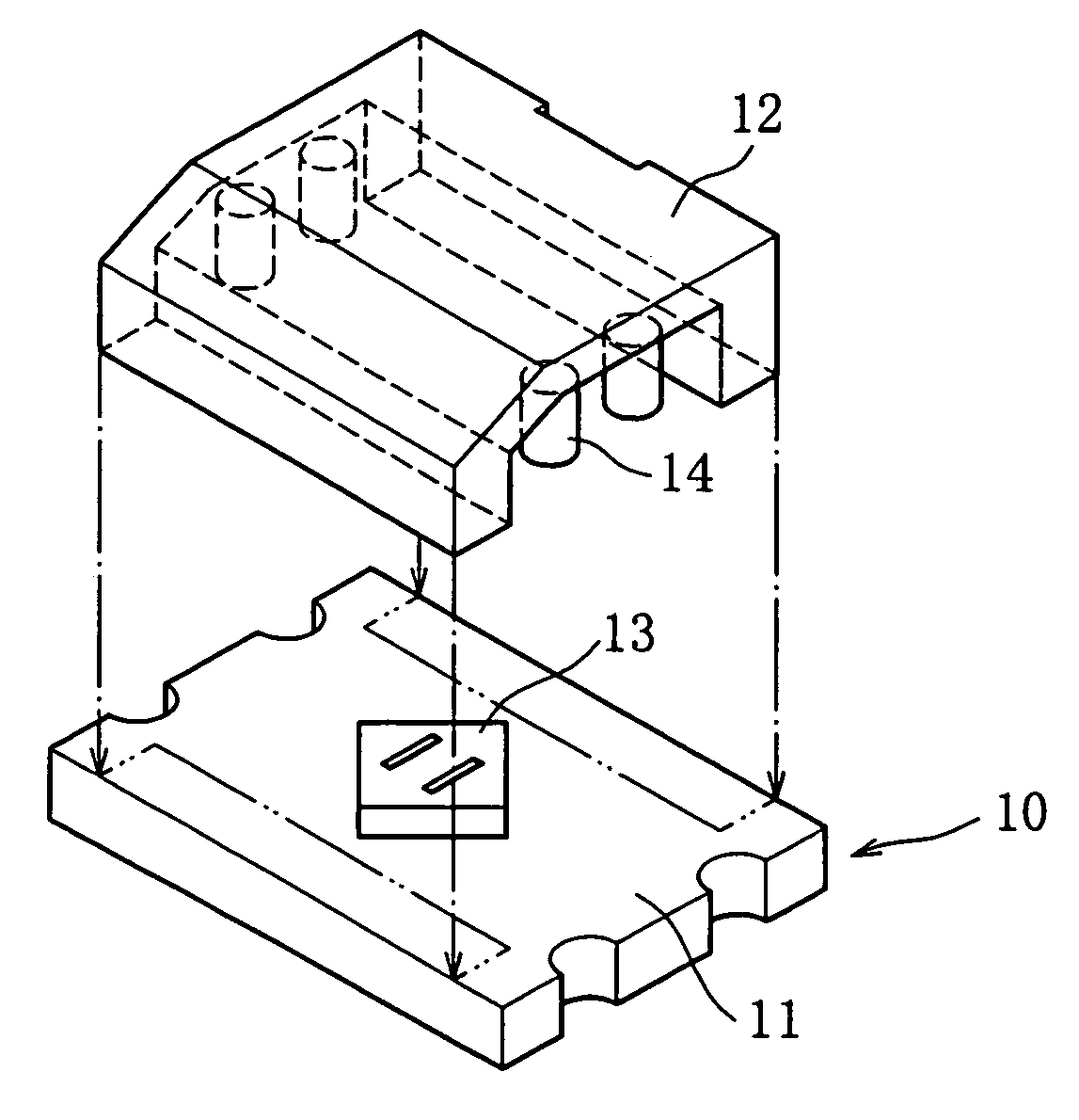
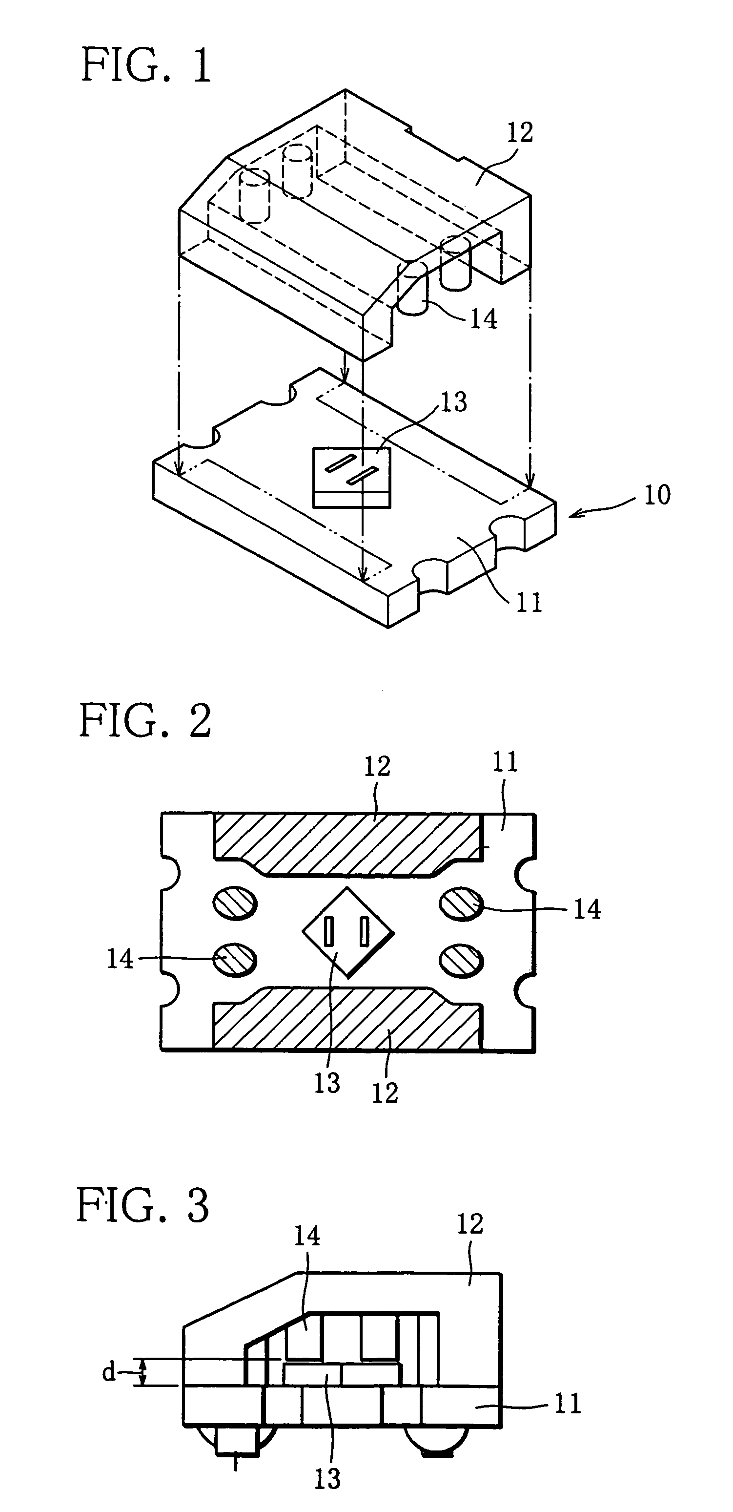
[0041]FIG. 1 is an exploded perspective view showing a schematic structure of a flowmeter according to an embodiment of the invention. Reference numeral 10 denotes a case which forms a predetermined flow passage. The case 10 comprises a slab-like lower case 11 and an upper case 12. The upper case 12 is joined to the upper surface of the lower case 11 integrally, so that a flow passage having an almost rectangular cross-section is formed between the upper and lower cases. A flow sensor 13 incorporated into the case 10 for detecting the flow rate of fluid such as gas or air flowing through the flow passage is, for example a thermal flow sensor described later, and arranged in the center of the upper surface of the lower case 11.

[0042]FIG. 2 shows a two-dimensional arrangement of the case 10, where part of the upper case 12 is cut away. As seen in FIG. 2, rod-like waste-material entry prev...


PUM


Abstract

A waste-material entry prevention member arranged upstream of a flow sensor is a rod- or plate-like member protruding halfway across the cross-section of a flow passage. Hence, vortexes or energy of the vortexes produced in fluid flowing by the waste-material entry prevention member is diffused by a stream of the fluid passing through a space left between the waste-material entry prevention member and the wall surface of the flow passage which the waste-material entry prevention member faces. Thus, production of vortexes is held down. Further, by making the flow sensor generate heat or heating the flow sensor, thermophoresis of the fluid is caused near the surface of the flow sensor. By this, particles contained in the fluid are prevented from accumulating on the flow sensor.

Description

CROSS-REFERENCE TO A RELATED APPLICATION[0001]This application claims priority on Japanese Patent Application No. 2002-379368 and Japanese Patent Application No. 2002-379369, the entire contents of which are hereby incorporated by reference.BACKGROUND OF THE INVENTION[0002]1. Field of the Invention[0003]The invention relates to a flowmeter of simple structure which can effectively prevent waste material from entering a flow passage in which a flow sensor is arranged, without disturbing a flow of fluid, and / or effectively prevent aerosol (particles) contained in fluid from adhering to the surface of a thermal flow sensor, and to a smoking device using this flowmeter.[0004]2. Description of the Related Art[0005]A sensor for detecting the flow rate of fluid such as gas or air, there is known a thermal flow sensor having a structure in which a pair of temperature measuring parts (temperature detecting elements) are arranged in the direction of flow of fluid with a predetermined space be...

Claims


Application Information

Patent Timeline
IPC IPC(8): G01F1/68G01F1/684G01F1/698G01F15/12
CPCG01F1/6842G01F15/12G01F1/6983
Inventor AOSHIMA, SHIGERUMATSUDA, JUNICHIWARASHINA, ISAMUOOISHI, YASUHARU
Owner YAMATAKE HONEYWELL CO LTD
Learn More