
Air quantity estimation apparatus for internal combustion engine

a technology of air quantity estimation and internal combustion engine, which is applied in the direction of machines/engines, electric control, instruments, etc., can solve the problems of increasing the calculation load of the microcomputer, the inability of the conventional apparatus to estimate the downstream pressure of the throttle valve with high accuracy

Inactive Publication Date: 2006-07-18
TOYOTA JIDOSHA KK
View PDF8 Cites 15 Cited by
  • Summary
  • Abstract
  • Description
  • Claims
  • Application Information

AI Technical Summary

Benefits of technology

The present invention provides an air quantity estimation apparatus for an internal combustion engine equipped with a supercharger. The apparatus accurately estimates the amount of air introduced into the cylinder by using a physical model that takes into account the behavior of air passing through the intake passage. The apparatus includes a throttle valve, a supercharger, a throttle valve downstream of the supercharger, and an intake valve. The apparatus uses a combination of pressure estimation means to accurately estimate the air quantity, including a throttle valve upstream pressure and a throttle valve downstream pressure. The apparatus also includes a selection condition determination means to determine when the selection conditions are satisfied, and a cylinder air quantity estimation means to estimate the air quantity introduced into the cylinder based on the throttle valve opening and the throttle valve downstream pressure. The apparatus can accurately estimate the air quantity even when the throttle valve is fully open, and can be used in an internal combustion engine equipped with a supercharger.

Problems solved by technology

Accordingly, the actual value of the function f(mt(t)), which represents the time derivative value of the throttle valve downstream pressure P(t), changes greatly, and thus, the conventional apparatus cannot estimate the throttle valve downstream pressure with high accuracy.
However, this method causes a problem that the calculation load of the microcomputer increases as the time step Δt decreases.

Method used


Image

  • Air quantity estimation apparatus for internal combustion engine
  • Air quantity estimation apparatus for internal combustion engine
  • Air quantity estimation apparatus for internal combustion engine

Examples


Embodiment Construction

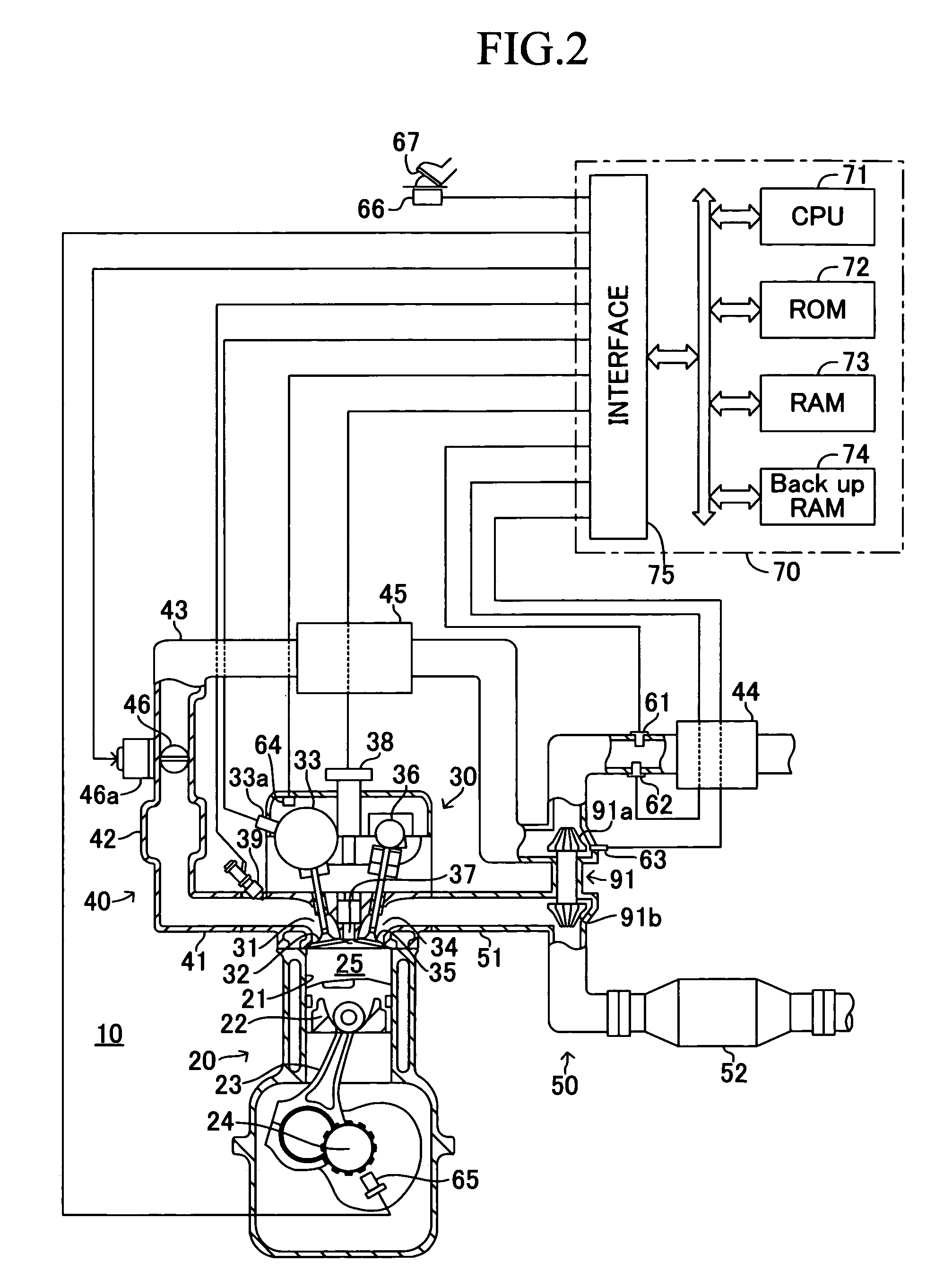
[0057]An air quantity estimation apparatus for an internal combustion engine according to an embodiment of the present invention will be described with reference to the drawings. FIG. 2 shows a schematic configuration of a system configured such that the air quantity estimation apparatus according to the present embodiment is applied to a spark-ignition multi-cylinder (e.g., 4-cylinder) internal combustion engine 10. Notably, FIG. 2 shows only a cross section of a specific cylinder; however the remaining cylinders have the same configuration.

[0058]The internal combustion engine 10 includes a cylinder block section 20 including a cylinder block, a cylinder block lower-case, an oil pan, etc.; a cylinder head section 30 fixed on the cylinder block section 20; an intake system 40 for supplying air-fuel mixture to the cylinder block section 20; and an exhaust system 50 for emitting exhaust gas from the cylinder block section 20 to the exterior of the engine 10.

[0059]The cylinder block se...


PUM


Abstract

An air quantity estimation apparatus for an internal combustion engine estimates intake pipe section pressure, which is pressure of air within an intake pipe section. When throttle valve opening is smaller than a threshold value, the apparatus estimates the intake pipe section pressure by use of an intercooler model constructed on the basis of conservation laws for air within the intercooler section and an intake pipe model constructed based on conservation laws for air within the intake pipe section. Meanwhile, when the throttle valve opening is greater than the threshold value, the apparatus estimates the intake pipe section pressure by use of an intercooler-intake pipe combined model constructed based on conservation laws for air within a combined section formed by combining the intercooler section and the intake pipe section. The apparatus estimates cylinder air quantity on the basis of the estimated intake pipe section pressure.

Description

BACKGROUND OF THE INVENTION[0001]1. Field of the Invention[0002]The present invention relates to an apparatus for estimating the quantity of air introduced into a cylinder of an internal combustion engine.[0003]2. Description of the Related Art[0004]Conventionally, there has been known an air quantity estimation apparatus for an internal combustion engine equipped with a supercharger which estimates cylinder air quantity, which is the quantity of air introduced into a cylinder of the engine, by use of a physical model representing behavior of air within an intake passage (refer to, for example, Japanese Kohyo (PCT) Patent Publication No. 2001-516421).[0005]One conventional apparatus of such a type estimates throttle valve downstream pressure P(t), which is the pressure of air as measured on the downstream side of a throttle valve and which changes with elapse of time t, on the basis of a differential equation (dP(t) / dt=f(mt(t))), wherein the time derivative term dP(t) / dt of the thro...

Claims


Application Information

Patent Timeline
Patent Type & Authority Patents(United States)
IPC IPC(8): F02D45/00F02B37/12G01F17/00
CPCF02D41/18F02D41/0007F02D2200/0408F02D2200/0404F02D2200/0402
Inventor TANAKA, SATORU
Owner TOYOTA JIDOSHA KK
Learn More